Anthony R. West - Solid State Chemistry and its Applications
Здесь есть возможность читать онлайн «Anthony R. West - Solid State Chemistry and its Applications» — ознакомительный отрывок электронной книги совершенно бесплатно, а после прочтения отрывка купить полную версию. В некоторых случаях можно слушать аудио, скачать через торрент в формате fb2 и присутствует краткое содержание. Жанр: unrecognised, на английском языке. Описание произведения, (предисловие) а так же отзывы посетителей доступны на портале библиотеки ЛибКат.
- Название:Solid State Chemistry and its Applications
- Автор:
- Жанр:
- Год:неизвестен
- ISBN:нет данных
- Рейтинг книги:4 / 5. Голосов: 1
-
Избранное:Добавить в избранное
- Отзывы:
-
Ваша оценка:
Solid State Chemistry and its Applications: краткое содержание, описание и аннотация
Предлагаем к чтению аннотацию, описание, краткое содержание или предисловие (зависит от того, что написал сам автор книги «Solid State Chemistry and its Applications»). Если вы не нашли необходимую информацию о книге — напишите в комментариях, мы постараемся отыскать её.
A comprehensive treatment of solid state chemistry complete with supplementary material and full colour illustrations from a leading expert in the field. Solid State Chemistry and its Applications, Second Edition
Student Edition
Significant updates and new content in this second edition include:
A more extensive overview of important families of inorganic solids including spinels, perovskites, pyrochlores, garnets, Ruddlesden-Popper phases and many more New methods to synthesise inorganic solids, including sol-gel methods, combustion synthesis, atomic layer deposition, spray pyrolysis and microwave techniques Advances in electron microscopy, X-ray and electron spectroscopies New developments in electrical properties of materials, including high Tc superconductivity, lithium batteries, solid oxide fuel cells and smart windows Recent developments in optical properties, including fibre optics, solar cells and transparent conducting oxides Advances in magnetic properties including magnetoresistance and multiferroic materials Homogeneous and heterogeneous ceramics, characterization using impedance spectroscopy Thermoelectric materials, MXenes, low dimensional structures, memristors and many other functional materials Expanded coverage of glass, including metallic and fluoride glasses, cement and concrete, geopolymers, refractories and structural ceramics Overview of binary oxides of all the elements, their structures, properties and applications Featuring full color illustrations throughout, readers will also benefit from online supplementary materials including access to CrystalMaker® software and over 100 interactive crystal structure models.
Perfect for advanced students seeking a detailed treatment of solid state chemistry, this new edition of
will also earn a place as a desk reference in the libraries of experienced researchers in chemistry, crystallography, physics, and materials science.
Solid State Chemistry and its Applications — читать онлайн ознакомительный отрывок
Ниже представлен текст книги, разбитый по страницам. Система сохранения места последней прочитанной страницы, позволяет с удобством читать онлайн бесплатно книгу «Solid State Chemistry and its Applications», без необходимости каждый раз заново искать на чём Вы остановились. Поставьте закладку, и сможете в любой момент перейти на страницу, на которой закончили чтение.
Интервал:
Закладка:
2 Rutile, TiO2, and CdI2 both have hcp anions (although the layers are buckled in rutile) with half the octahedral sites occupied by cations but they differ in the manner of occupancy of these octahedral sites. In rutile, half the octahedral sites between any pair of cp anion layers are occupied by Ti. In CdI2, layers of fully occupied octahedral sites alternate with layers in which all sites are empty; this gives CdI2 a layered structure.
3 In a few structures, it is useful to regard the cation as forming the cp layers with the anions occupying the interstitial sites. The fluorite structure, CaF2, may be regarded as ccp Ca with all T+ and T– sites occupied by F. The antifluorite structure of K2O is the exact inverse of fluorite with ccp layers of O and K in T+, T– sites; it is included in Table 1.4.
4 The cp concept may be extended to structures in which a mixture of anions and large cations form the packing layers and smaller cations occupy interstitial sites. In perovskite, BaTiO3, ccp layers of composition ‘BaO3’ occur and one‐quarter of the octahedral sites between these layers are occupied by Ti, although only those sites in which all six corners are O2– ions.
5 Some structures are anion‐deficient cp structures in which the anions form an incomplete cp array. The ReO3 structure has ccp oxide layers with one‐quarter of the O sites empty. It is analogous to perovskite just described in which Ti is replaced by Re and Ba sites are left vacant. The structure of β‐alumina, nominally of formula NaAl11O17, contains cp oxide layers in which every fifth layer has approximately three‐quarters of the O2– ions missing.
1.15.3.2 Relative sizes of tetrahedral and octahedral sites
A general guideline is that tetrahedra are smaller than octahedra which, in turn, are smaller than polyhedra of higher coordination number; for a given anion array, the relative sizes of sites may be obtained quantitatively by geometric calculations (see the next section). In ionic structures, cations M occupy those sites or polyhedra of most suitable size. Cations may occupy sites which, at first sight, appear too small, by pushing apart anions and expanding the structure (as in eutactic structures). By contrast, cations tend not to occupy sites that are too large, unless the structure can adjust itself, by twisting or distorting the anion array so as to reduce the size of the sites; this happens in many distorted perovskite structures in which cations are too small to occupy large 12‐coordinate sites and a partial structural collapse occurs (see Section 1.17.7). Thus, cations do not occupy large sites in which they can ‘rattle’. An interesting intermediate situation occurs in some structures in which a cation site is marginally too large. The cation can then undergo small off‐centre displacements giving rise to high polarisability, high permittivity and the phenomenon of ferroelectricity (Section 8.7).
1.15.3.3 Location of tetrahedral and octahedral sites in an fcc unit cell; bond length calculations
We have seen how T +, T –and O sites occur between pairs of cp layers, Fig. 1.23, and how fcc and ccp structures are often equivalent, Fig. 1.20. We can now see where the T +, T –and O sites are located within an fcc unit cell that has anions, X, at corners and face centres (A, B, C, and D), Fig. 1.24. The octahedral sites are easiest to locate; they are at edge‐centre 1, 2, 3 and body‐centre 4 positions. If the unit cell has length a, the M–X distance for octahedral sites is a /2.
In order to see the T +, T –sites clearly, it is convenient to divide the unit cell into eight minicubes by bisecting each cell edge (dashed lines). These minicubes contain anions at only four of the eight corners; in the middle of each minicube is a tetrahedral site, either T +or T –. There are two orientations for the minicubes, and therefore for the T sites, as shown in Fig. 1.25; relative to the parent unit cell, Fig. 1.24, the T –tetrahedra have their apices pointing in the [  ] direction and the T +sites in the [111] direction.
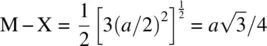
At this point, we note that it is exceptionally useful to be able to regard a tetrahedral site as occupying the centre of a cube with alternate corners absent, Fig. 1.25(a) and (b). For such an arrangement, it is easy to calculate bond lengths and bond angles (c) and to demonstrate the various symmetry elements associated with a tetrahedron. Thus, for the minicube of edge dimension a/ 2,
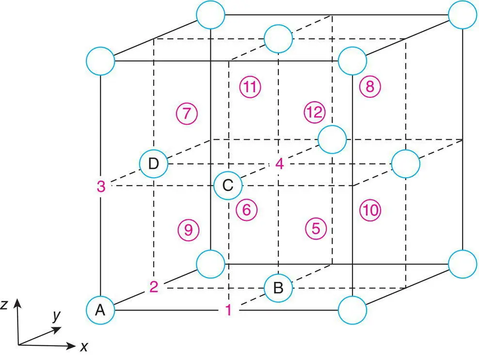
Figure 1.24 Available cation sites, 1–12, in an fcc anion array.
Twofold rotation axes and fourfold inversion axes run parallel to minicube edges but pass through pairs of opposite faces; there are three of these in total (see also Fig. 1.7c); mirror planes occur parallel to the set of lattice planes with indices {110}, and there are six of these in total [as in Fig. 1.9(c)]; threefold axes run parallel to <111> directions, four in total, Fig. 1.9(a); further details are in Appendix C.
1.15.3.4 Description of crystal structures; fractional atomic coordinates
In order to describe crystal structures, it is necessary to specify (a) the unit cell type, (b) its dimensions and (c) the fractional coordinates of the atoms in the unit cell. As described earlier, an fcc unit cell containing anions at corner and face centre positions has, effectively, four anions in the unit cell, one at a corner and three at face centres. The fractional coordinates of the four anions A–D in the unit cell, Fig. 1.24, are
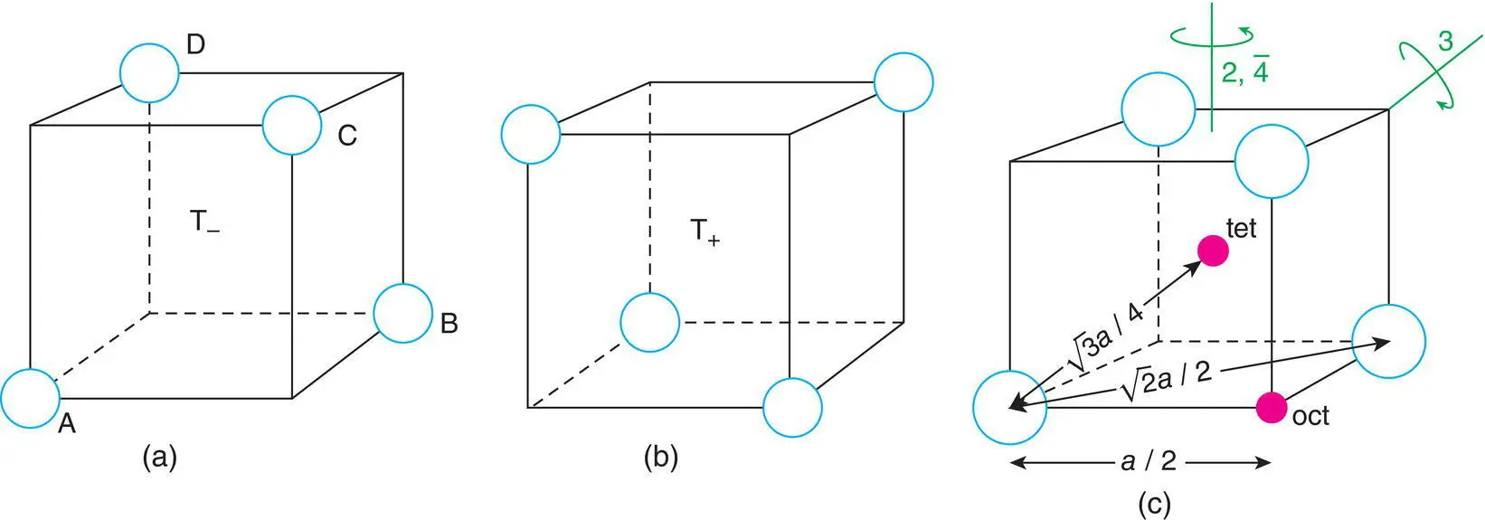
Figure 1.25 (a, b) Tetrahedral sites T+, T– and their relation to a cube. (c) Bond length calculations and some symmetries of a tetrahedron.
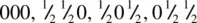
Only one corner, at 000, is included since the other seven, e.g. at 100, 010, etc., are equivalent and can be regarded as the corner atoms of adjacent cells. The alternative would be to list all eight corner atoms, with the qualification that only 1/8 of each belonged to the unit cell in question. This would be equivalent to, but much more cumbersome than, regarding one corner only as specifically belonging, completely, to our unit cell. Likewise, for each pair of opposite faces, e.g. ½½0 and ½½1 , it is most convenient to regard ½½0 as belonging completely to our unit cell; ½½1 then becomes the bottom face centre in the cell above.
The various cation positions in Fig. 1.24 have the following coordinates:
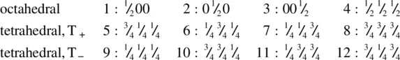
Note that there are four of each type of cation site, O, T +, T –, in the unit cell, together with four anions. When different sites are fully or partially occupied by the cations, different structures are generated, as indicated in Table 1.4and discussed later.
Читать дальшеИнтервал:
Закладка:
Похожие книги на «Solid State Chemistry and its Applications»
Представляем Вашему вниманию похожие книги на «Solid State Chemistry and its Applications» списком для выбора. Мы отобрали схожую по названию и смыслу литературу в надежде предоставить читателям больше вариантов отыскать новые, интересные, ещё непрочитанные произведения.


Обсуждение, отзывы о книге «Solid State Chemistry and its Applications» и просто собственные мнения читателей. Оставьте ваши комментарии, напишите, что Вы думаете о произведении, его смысле или главных героях. Укажите что конкретно понравилось, а что нет, и почему Вы так считаете.