Anthony R. West - Solid State Chemistry and its Applications
Здесь есть возможность читать онлайн «Anthony R. West - Solid State Chemistry and its Applications» — ознакомительный отрывок электронной книги совершенно бесплатно, а после прочтения отрывка купить полную версию. В некоторых случаях можно слушать аудио, скачать через торрент в формате fb2 и присутствует краткое содержание. Жанр: unrecognised, на английском языке. Описание произведения, (предисловие) а так же отзывы посетителей доступны на портале библиотеки ЛибКат.

- Название:Solid State Chemistry and its Applications
- Автор:
- Жанр:
- Год:неизвестен
- ISBN:нет данных
- Рейтинг книги:4 / 5. Голосов: 1
-
Избранное:Добавить в избранное
- Отзывы:
-
Ваша оценка:
Solid State Chemistry and its Applications: краткое содержание, описание и аннотация
Предлагаем к чтению аннотацию, описание, краткое содержание или предисловие (зависит от того, что написал сам автор книги «Solid State Chemistry and its Applications»). Если вы не нашли необходимую информацию о книге — напишите в комментариях, мы постараемся отыскать её.
A comprehensive treatment of solid state chemistry complete with supplementary material and full colour illustrations from a leading expert in the field. Solid State Chemistry and its Applications, Second Edition
Student Edition
Significant updates and new content in this second edition include:
A more extensive overview of important families of inorganic solids including spinels, perovskites, pyrochlores, garnets, Ruddlesden-Popper phases and many more New methods to synthesise inorganic solids, including sol-gel methods, combustion synthesis, atomic layer deposition, spray pyrolysis and microwave techniques Advances in electron microscopy, X-ray and electron spectroscopies New developments in electrical properties of materials, including high Tc superconductivity, lithium batteries, solid oxide fuel cells and smart windows Recent developments in optical properties, including fibre optics, solar cells and transparent conducting oxides Advances in magnetic properties including magnetoresistance and multiferroic materials Homogeneous and heterogeneous ceramics, characterization using impedance spectroscopy Thermoelectric materials, MXenes, low dimensional structures, memristors and many other functional materials Expanded coverage of glass, including metallic and fluoride glasses, cement and concrete, geopolymers, refractories and structural ceramics Overview of binary oxides of all the elements, their structures, properties and applications Featuring full color illustrations throughout, readers will also benefit from online supplementary materials including access to CrystalMaker® software and over 100 interactive crystal structure models.
Perfect for advanced students seeking a detailed treatment of solid state chemistry, this new edition of
will also earn a place as a desk reference in the libraries of experienced researchers in chemistry, crystallography, physics, and materials science.
Solid State Chemistry and its Applications — читать онлайн ознакомительный отрывок
Ниже представлен текст книги, разбитый по страницам. Система сохранения места последней прочитанной страницы, позволяет с удобством читать онлайн бесплатно книгу «Solid State Chemistry and its Applications», без необходимости каждый раз заново искать на чём Вы остановились. Поставьте закладку, и сможете в любой момент перейти на страницу, на которой закончили чтение.
Интервал:
Закладка:
In a 3D cp structure, each sphere is in contact with 12 others, and this is the maximum coordination number possible for contacting and equal‐sized spheres. [A common non‐ cp structure is the body centred cube, e.g. in α ‐Fe, with a coordination number of eight; see Fig. 1.11(e).] Six of these neighbours are coplanar with the central sphere, Fig. 1.16(a); from Fig. 1.17 and Fig. 1.18, the remaining six are in two groups of three spheres, one in the plane above and one in the plane below (Fig. 1.19); hcp and ccp differ in the relative orientations of these two groups of three neighbours.
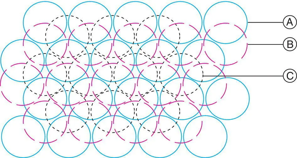
Figure 1.18 Three close packed layers in ccp sequence.
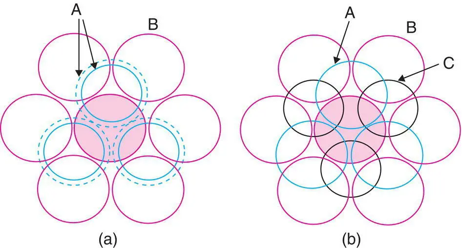
Figure 1.19 Coordination number 12 of shaded sphere in (a) hcp and (b) ccp structures. The shaded sphere is in the B layer, the layer underneath is A, and the layer above is either (a) A or (b) C.
Many structures, not just of metals and alloys, but also ionic, covalent and molecular structures, can be described using close packing ideas. Sometimes the atoms that form the cp array are as closely packed as possible, but in other cases their arrangement is as in cp but the atoms are clearly not touching. Such structures are known as eutactic structures. Some guidelines as to whether it is appropriate to consider a structure in terms of a cp arrangement are given in Appendix D.
1.11 Relationship Between Cubic Close Packed and Face Centred Cubic
The unit cell of a ccp arrangement is the familiar face centred cubic ( fcc ) unit cell, Fig. 1.11(c), with spheres at corner and face centre positions. The relation between ccp and fcc is not immediately obvious since the faces of the fcc unit cell do not correspond to cp layers. The cp layers are, instead, parallel to the {111} planes of the fcc unit cell. This is shown in Fig. 1.20 and Appendix B. The spheres labelled 2–7 in Fig. 1.20(a) form part of a cp layer, as revealed by removing a corner sphere 1 in (b) and comparing (b) with Fig. 1.16(a). The orientations of (a) and (b) in Fig. 1.20 are the same but the spheres in (b) are shown larger. A similar arrangement to that shown in (b) would be seen on removing any corner sphere in (a) and, therefore, in a ccp structure, cp layers occur in four orientations. These orientations are perpendicular to the body diagonals of the cube (the cube has eight corners but only four body diagonals and, hence, four different orientations of the cp layers). The cp layers in one orientation are seen edge‐on in (c) and in another orientation, perpendicular to the layers in (d); (c) is the same as (a) but rotated slightly; similarly, (d) is the same as (b) but also rotated slightly. In (d), all atoms of the unit cell, spanning four cp layers, ABCA, are shown in projection down a <111> direction.
1.12 Hexagonal Unit Cell and Close Packing
An hcp arrangement of spheres has a hexagonal unit cell (Fig. 1.21). The basal plane of the cell coincides with a cp layer of spheres (b). The unit cell contains two spheres, one at the origin (and hence at all corners) and one inside the cell at positions ⅔, ⅓, ½ [pink circle in (a) and (b)]. Note that although the two a axes of the basal plane are equal, we need to distinguish them by a 1and a 2for the purpose of describe atomic coordinates of the positions ⅔, ⅓, ½. The use of such fractional coordinates to represent positions of atoms inside a unit cell is discussed later.
cp layers occur in only one orientation in an hcp structure. These are parallel to the basal plane, as shown for one layer in Fig. 1.21(b). The two axes in the basal plane are of equal length; a = 2 r , if the spheres of radius r touch; the angle Γ is 120° (Table 1.1).
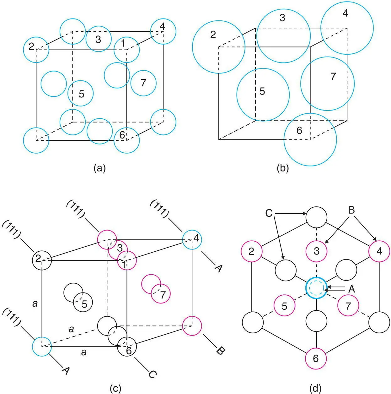
Figure 1.20 Face centred cubic, fcc, unit cell of a ccp arrangement of spheres.
The symmetry of the hexagonal unit cell is deceptively simple. The basal plane in isolation has a sixfold rotation axis but the adjacent B layer along the c axis reduces this to threefold rotational symmetry, as shown in Fig. 1.21(c): note the crystallographic symbol for a threefold axis, which is a solid triangle.
The structure does, however, possess a 6 3screw axis parallel to c and passing through the basal plane at the coordinate position ⅓, ⅔, 0, as shown in Fig. 1.21(d). This symmetry axis involves a combined step of translation by c /2 and rotation by 60°; atoms labelled 1–6 lie on a spiral with increasing c height above the basal plane; thus, atom 3 is on the top face of the unit cell whereas 4 and 5 are in the next unit cell in the c direction. Hence the hcp crystal structure has both a sixfold screw axis and a threefold rotation axis.
The hcp crystal structure has many other symmetry elements as well, including a nice example of a glide plane as shown in Fig. 1.21(e); the components of this c ‐glide involve displacement in the c direction by c /2 and reflection across the a 1 c plane that passes through the unit cell with a 2coordinate ⅔, as shown by the dotted line (crystallographic symbol for a c ‐glide plane). Thus, atoms labelled 1, 2, 3, 4, etc. are related positionally to each other by this glide plane.
1.13 Density of Close Packed Structures
In cp structures, 74.05% of the total volume is occupied by spheres. This is the maximum density possible in structures constructed of spheres of only one size. This value may be calculated from the volume and contents of the unit cell. In a ccp array of spheres, the fcc unit cell contains four spheres, one at a corner and three at face centre positions, Fig. 1.20 (this is equivalent to the statement that a fcc unit cell contains four lattice points). cp directions [ xx ′, yy ′, zz ′ in Fig. 1.16(a)], in which spheres are in contact, occur parallel to the face diagonals of the unit cell, e.g. spheres 2, 5 and 6 in Fig. 1.20(b) form part of a cp row. The length of the face diagonal is therefore 4 r . From the Pythagoras theorem, the length of the cell edge is then  and the cell volume is
  , Fig. 1.22 (a). The volume of each sphere is 1.33 πr 3and so the ratio of the total sphere volume to the unit cell volume is given by
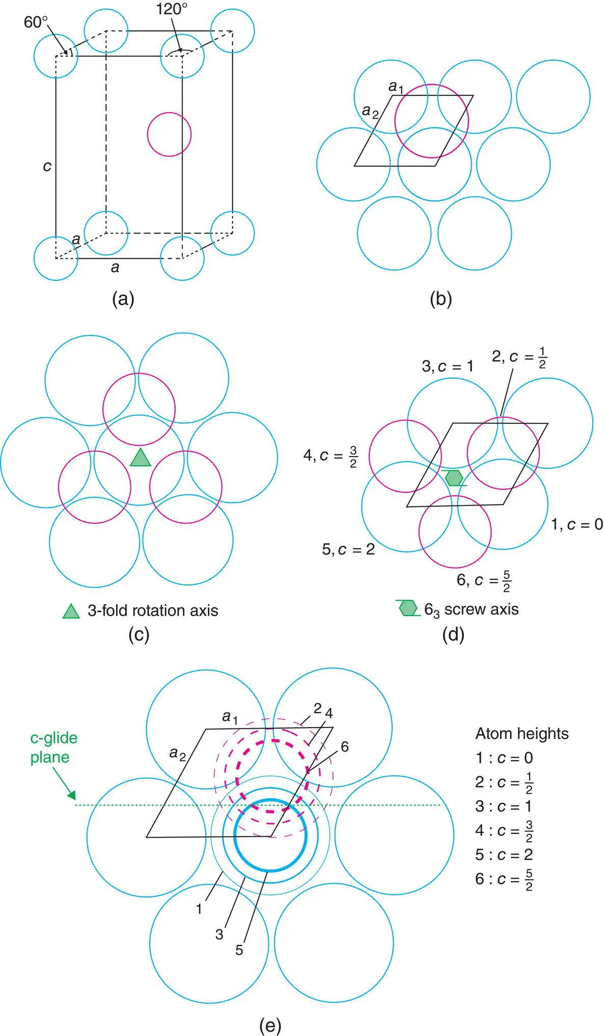
Figure 1.21 (a, b) Hexagonal unit cell of an hcp arrangement of spheres showing (c) a threefold rotation axis, (d) a 63 screw axis, and (e) a c‐glide plane.
Читать дальшеИнтервал:
Закладка:
Похожие книги на «Solid State Chemistry and its Applications»
Представляем Вашему вниманию похожие книги на «Solid State Chemistry and its Applications» списком для выбора. Мы отобрали схожую по названию и смыслу литературу в надежде предоставить читателям больше вариантов отыскать новые, интересные, ещё непрочитанные произведения.


Обсуждение, отзывы о книге «Solid State Chemistry and its Applications» и просто собственные мнения читателей. Оставьте ваши комментарии, напишите, что Вы думаете о произведении, его смысле или главных героях. Укажите что конкретно понравилось, а что нет, и почему Вы так считаете.