Anthony R. West - Solid State Chemistry and its Applications
Здесь есть возможность читать онлайн «Anthony R. West - Solid State Chemistry and its Applications» — ознакомительный отрывок электронной книги совершенно бесплатно, а после прочтения отрывка купить полную версию. В некоторых случаях можно слушать аудио, скачать через торрент в формате fb2 и присутствует краткое содержание. Жанр: unrecognised, на английском языке. Описание произведения, (предисловие) а так же отзывы посетителей доступны на портале библиотеки ЛибКат.

- Название:Solid State Chemistry and its Applications
- Автор:
- Жанр:
- Год:неизвестен
- ISBN:нет данных
- Рейтинг книги:4 / 5. Голосов: 1
-
Избранное:Добавить в избранное
- Отзывы:
-
Ваша оценка:
Solid State Chemistry and its Applications: краткое содержание, описание и аннотация
Предлагаем к чтению аннотацию, описание, краткое содержание или предисловие (зависит от того, что написал сам автор книги «Solid State Chemistry and its Applications»). Если вы не нашли необходимую информацию о книге — напишите в комментариях, мы постараемся отыскать её.
A comprehensive treatment of solid state chemistry complete with supplementary material and full colour illustrations from a leading expert in the field. Solid State Chemistry and its Applications, Second Edition
Student Edition
Significant updates and new content in this second edition include:
A more extensive overview of important families of inorganic solids including spinels, perovskites, pyrochlores, garnets, Ruddlesden-Popper phases and many more New methods to synthesise inorganic solids, including sol-gel methods, combustion synthesis, atomic layer deposition, spray pyrolysis and microwave techniques Advances in electron microscopy, X-ray and electron spectroscopies New developments in electrical properties of materials, including high Tc superconductivity, lithium batteries, solid oxide fuel cells and smart windows Recent developments in optical properties, including fibre optics, solar cells and transparent conducting oxides Advances in magnetic properties including magnetoresistance and multiferroic materials Homogeneous and heterogeneous ceramics, characterization using impedance spectroscopy Thermoelectric materials, MXenes, low dimensional structures, memristors and many other functional materials Expanded coverage of glass, including metallic and fluoride glasses, cement and concrete, geopolymers, refractories and structural ceramics Overview of binary oxides of all the elements, their structures, properties and applications Featuring full color illustrations throughout, readers will also benefit from online supplementary materials including access to CrystalMaker® software and over 100 interactive crystal structure models.
Perfect for advanced students seeking a detailed treatment of solid state chemistry, this new edition of
will also earn a place as a desk reference in the libraries of experienced researchers in chemistry, crystallography, physics, and materials science.
Solid State Chemistry and its Applications — читать онлайн ознакомительный отрывок
Ниже представлен текст книги, разбитый по страницам. Система сохранения места последней прочитанной страницы, позволяет с удобством читать онлайн бесплатно книгу «Solid State Chemistry and its Applications», без необходимости каждый раз заново искать на чём Вы остановились. Поставьте закладку, и сможете в любой момент перейти на страницу, на которой закончили чтение.
Интервал:
Закладка:
The structures of materials such as NaCl, Al 2O 3, Na 2O and ZnO, in which the anion is larger than the cation, are built of cp layers of anions with the cations placed in interstitial sites . Many structures are possible in which the variables are the anion stacking sequence, either hcp or ccp, and the number and type of interstitial sites occupied by cations. The cations are, however, often too large for the prescribed interstitial sites and the structure can accommodate them only by expanding the anion array. Consequently, the anion arrangement is the same as in cp, but the anions may not be in contact. O'Keeffe suggested the term eutactic for structures such as these. In the discussions that follow, use of the terms hcp and ccp for the anion arrays does not necessarily imply that the anions are in contact but rather that the structures are eutactic. A further complication, as we shall see later, is that the rigid sphere model is an oversimplification of reality since, in ionic structures, it can be difficult to specify ion sizes exactly.
It is useful at this stage to identify the criteria for an ionic structure to be regarded as close packed, since both cation and anion arrangements are involved. As with metal structures, the first criterion is that close packed anions exist with a coordination number, by other anions, of twelve. Six of these should be co‐planar, forming cp layers, as in Fig. 1.16(a). The other six form part of two cp layers to either side ; the relative orientation of these two layers determines the overall stacking sequence, whether ccp or hcp .
Various departures from ideal cp structures occur. Thus, in some structures, such as solid solutions or doped materials, anion vacancies may be present, within the overall cp array. These vacancies are usually at random throughout the anion array, such as in the perovskite (La 1−xSr x)(Ga 1−xMg x)O 3−x, but the ordering of oxygen vacancies may occur as in, for example, the beta alumina family of structures in which every fifth layer in a cp oxide sequence has ¾ of the oxygens missing, Fig. 8.23. In other cp structures, particularly those containing large cations such as K +, Sr 2+or La 3+in perovskites, mixed cp layers are present because these cations are large enough to be surrounded by 12 anion neighbours. Thus, in SrTiO 3, Sr and O together form a ccp sequence in which the Sr and O positions are ordered rather than randomised, Fig. 1.41(e). And in some other structures, especially fluorite, the cations rather than the anions form a cp array. Finally, the structures may be eutactic in that the cp arrangement of one type of ion is clearly present, but the ions are pushed apart and therefore, the structures are not closest packed.
Within a cp anion array, interstitial sites for cations are restricted to either tetrahedral or octahedral, as discussed next. For the anion coordination number, however, there is no such limitation. Although the anion–anion coordination number (above) is twelve, this refers to the second coordination sphere around a particular anion whereas the anion–cation coordination number refers to the primary coordination sphere, with the smallest interatomic distances. Various examples of anion–cation coordination numbers and arrangements are given throughout this chapter, as well as examples of structures that are distorted away from an ideal cp arrangement. First, we consider the cases of the standard tetrahedral and octahedral coordinations.
1.15.3.1 Tetrahedral and octahedral sites
Two types of interstitial site, tetrahedral and octahedral, are present in cp structures, Fig. 1.23. These may be seen by considering the nature of the interstitial space between any pair of adjacent cp layers. For the tetrahedral sites, three anions that form the base of the tetrahedron belong to one cp layer with the apex of the tetrahedron either in the layer above (a) or below (b). This gives two orientations of tetrahedral sites, T +and T –, in which the apex is up and down, respectively, and is illustrated further in (c) and (d) with the layers seen edge‐on. Because the centre of gravity of a tetrahedron is nearer to the base than the apex (see Appendix C), cations in tetrahedral sites are not located midway between adjacent anion layers but are nearer one layer than the other. In ccp structures, there are four equivalent orientations of cp layers and therefore, four equivalent orientations of T +, T –sites
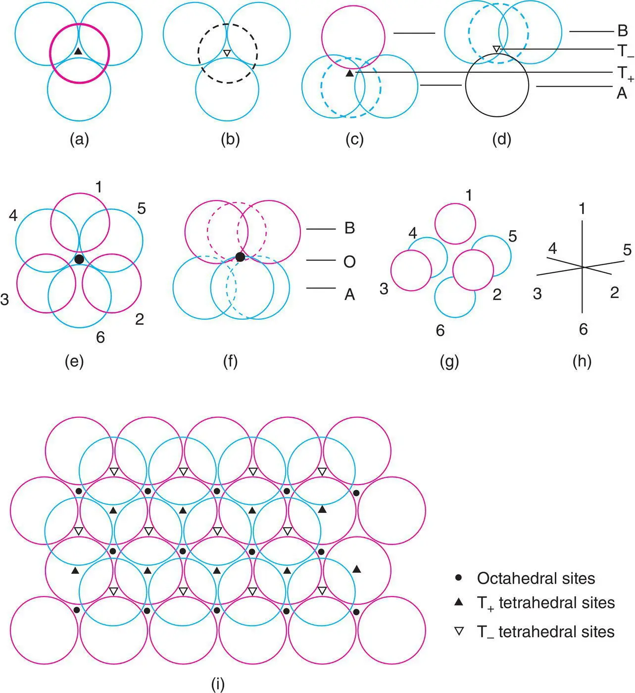
Figure 1.23 Tetrahedral and octahedral sites between two cp anion layers, seen from different perspectives. (a, b) Projection down threefold axis of T+, T– sites. (c, d) Tetrahedral sites edge‐on. (e) Projection down threefold axis of octahedral site and (f) seen edge‐on. (g, h) Conventional representation of octahedral site. (i) Distribution of T+, T–, O sites between two cp layers. The labelling of tetrahedral sites as T+ and T− is arbitrary and is only to indicate that there are two possible different orientations for these sites.
Octahedral sites, O, are coordinated to three anions in each layer, Fig. 1.23(e) and are midway between the anion layers (f). A more common way to regard octahedral coordination is as four coplanar atoms with one atom at each apex above and below the plane. In (e), atoms 1, 2, 4 and 6 are coplanar; 3 and 5 form apices of the octahedron. Also, atoms 2, 3, 4, 5 and 1, 3, 5, 6 are coplanar. This is further illustrated in Fig. 1.23(g) and (h), which are similar to (e) but seen from a different and more conventional perspective.
The distribution of interstitial sites between any two adjacent layers of cp anions is shown in Fig. 1.23(i). We can see that below every red sphere in the upper layer is a T +site; likewise above every blue sphere in the lower layer is a T –site. There are also as many O sites as either T +or T –sites. A similar distribution to that in (i) is seen between each pair of cp anion layers. Counting up the numbers of each, then, for every anion there is one octahedral site and two tetrahedral sites, one T +and one T –.
It is rare that all the interstitial sites in a cp structure are occupied; often one set is full or partly occupied and the remaining sets are empty. A selection of cp ionic structures, classified according to the anion layer stacking sequence and the occupancy of the interstitial sites, is given in Table 1.4. Individual structures are described later. Here we simply note how a wide range of structures are grouped into one large family; this helps to bring out similarities and differences between them. For example:
1 The rock salt and nickel arsenide structures both have octahedrally coordinated cations and differ only in the anion stacking sequence. Similarly, there are other pairs of structures with similar cation coordination numbers that differ only in the anion stacking sequence, e.g. olivine and spinel, wurtzite and zinc blende, CdI2 and CdCl2. Table 1.4Some close packed structuresAnion arrangementInterstitial sitesExamplesT+T–Occp––1NaCl, rock salt1––ZnS, blende, or sphalerite1/81/81/2MgAl2O4, spinel––1/2CdCl2––1/3CrCl311–K2O, antifluoritehcp––1NiAs1––ZnS, wurtzite––1/2CdI2––1/2TiO2, rutile a ––2/3α‐Al2O3, corundum1/81/81/2Mg2SiO4, olivineccp ‘BaO3’ layers––1/4BaTiO3, perovskite a The hcp oxide layers in rutile are not planar but are buckled; the oxide arrangement may alternatively be described as tetragonal packed, tp.
Читать дальшеИнтервал:
Закладка:
Похожие книги на «Solid State Chemistry and its Applications»
Представляем Вашему вниманию похожие книги на «Solid State Chemistry and its Applications» списком для выбора. Мы отобрали схожую по названию и смыслу литературу в надежде предоставить читателям больше вариантов отыскать новые, интересные, ещё непрочитанные произведения.


Обсуждение, отзывы о книге «Solid State Chemistry and its Applications» и просто собственные мнения читателей. Оставьте ваши комментарии, напишите, что Вы думаете о произведении, его смысле или главных героях. Укажите что конкретно понравилось, а что нет, и почему Вы так считаете.