Mark Middlebrook - AutoCAD 2005 for Dummies
Здесь есть возможность читать онлайн «Mark Middlebrook - AutoCAD 2005 for Dummies» — ознакомительный отрывок электронной книги совершенно бесплатно, а после прочтения отрывка купить полную версию. В некоторых случаях можно слушать аудио, скачать через торрент в формате fb2 и присутствует краткое содержание. Город: Indianapolis, Год выпуска: 2004, ISBN: 2004, Издательство: Wiley Publishing, Inc, Жанр: Программы, на английском языке. Описание произведения, (предисловие) а так же отзывы посетителей доступны на портале библиотеки ЛибКат.

- Название:AutoCAD 2005 for Dummies
- Автор:
- Издательство:Wiley Publishing, Inc
- Жанр:
- Год:2004
- Город:Indianapolis
- ISBN:0-7645-7138-9
- Рейтинг книги:5 / 5. Голосов: 1
-
Избранное:Добавить в избранное
- Отзывы:
-
Ваша оценка:
AutoCAD 2005 for Dummies: краткое содержание, описание и аннотация
Предлагаем к чтению аннотацию, описание, краткое содержание или предисловие (зависит от того, что написал сам автор книги «AutoCAD 2005 for Dummies»). Если вы не нашли необходимую информацию о книге — напишите в комментариях, мы постараемся отыскать её.
AutoCAD is more than just another application program, it’s a complete environment for drafting and design. So if you’re new to AutoCAD, you need to know several things to get off to a good start — especially how to use the command line area and set up your drawing properly. These key techniques are described in this part of the book.
If you’ve used earlier versions of AutoCAD, you’ll be most interested in the high points of the new release, including some newer interface components. The lowdown on what’s new is here, too.
AutoCAD 2005 for Dummies — читать онлайн ознакомительный отрывок
Ниже представлен текст книги, разбитый по страницам. Система сохранения места последней прочитанной страницы, позволяет с удобством читать онлайн бесплатно книгу «AutoCAD 2005 for Dummies», без необходимости каждый раз заново искать на чём Вы остановились. Поставьте закладку, и сможете в любой момент перейти на страницу, на которой закончили чтение.
Интервал:
Закладка:
□ Radial dimensions:A radius dimension calls out the radius of a circle or arc, and a diameter dimension calls out the diameter of a circle or arc. You can position the dimension text inside or outside the curve, as shown in Figure 10-3. If you position the text outside the curve, AutoCAD by default draws a little cross at the center of the circle or arc.
□ Angular dimensions:An angular dimension calls out the angular measurement between two lines, the two endpoints of an arc, or two points on a circle. The dimension line appears as an arc that indicates the sweep of the measured angle.
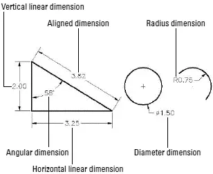
Figure 10-3:Common types of dimensions.
Other types of AutoCAD dimensions include ordinate, tolerance, center mark, and leader dimensions. See the “Pointy-Headed Leaders” section at the end of this chapter for instructions on how to draw leaders. Look up “dimensions, creating” on the Index tab in the AutoCAD online help system for more information about other kinds of dimensions.
By default, AutoCAD groups all the parts of each dimension — the extension lines, dimension lines, arrowheads, and text — into a special associative dimension object. Associative means two things:
□ The different parts of the dimension function as a single object. When you click any part of the dimension, AutoCAD selects all of its parts.
□ The dimension is connected with the points on the object that you specified when you drew the dimension. If you change the size of the object (for example, stretch a line), the dimension updates appropriately — the lines and arrows move, and the text changes to reflect the line’s new size.
I call dimensions with both of these characteristics geometry-driven associative dimensions, because the geometry “drives” the location of the parts of the dimension and what the text says.
 For historical reasons, AutoCAD also is capable of creating dimensions that possess just the first type of associativity — that is, the dimension functions as a single, grouped object but isn’t directly connected with the object whose size it shows. Autodesk now calls these kinds of dimensions nonassociative, which is pretty confusing to AutoCAD veterans, because AutoCAD used to call them associative! AutoCAD also is capable of creating dimensions that possess no type of associativity at all — no grouping of the bits and pieces and no connection to the dimensioned object. Autodesk now calls these exploded dimensions, but before AutoCAD 2002, they were called nonassociative!
I mention the conflicting use of associative and nonassociative in case you find yourself discussing dimensions with AutoCAD veterans, most of whom will use the terms in their older sense. To avoid confusion, I always use the term geometry-driven associative dimensions (or simply geometry-driven dimensions ) in this book to refer to dimensions that possess both types of associativity. For more information about how to determine which kind of dimension AutoCAD draws, see “Controlling and editing dimension associativity,” later in this chapter.
The AutoCAD Dimension menu provides access to dimensioning commands. If you find yourself adding dimensions in batches, the Dimension toolbar is more efficient because it makes the dimensioning commands more accessible. You toggle the Dimension toolbar off and on by right-clicking any AutoCAD toolbar icon and choosing Dimension from the cursor menu. As with other toolbars, you can move the Dimension toolbar to a different location on the screen or dock it on any margin of the drawing area.
All dimensioning commands have long command names (such as DIMLINEAR and DIMRADIUS) and corresponding shortened abbreviations (DLI and DRA) that you can type at the command prompt. If you do lots of dimensioning and don’t want to toggle the Dimension toolbar on and off repeatedly, memorize the abbreviated forms of the dimension commands that you use frequently. You’ll find a list of the long command names on the Contents tab in the AutoCAD online help system. Choose Command Reference→Commands→D Commands. The short names are the first, fourth, and fifth letters of the long names. (In other words, take the first five letters of the long name and remove IM. )
Doing Dimensions with Style(s)
Creating a usable dimension style that gives you the dimension look you want is the biggest challenge in using AutoCAD’s dimensioning features. Each drawing contains its own dimension styles, so changes you make to a dimension style in one drawing affect only that drawing. However, after you get the dimension styles right in a drawing, you can use it as a template or starting point for later drawings.
A dimension style is a collection of drawing settings called dimension variables, which are a special class of the system variables that I introduce in Chapter 2.
If you want to see a list of the dimension variable names and look up what each variable controls, see Contents→Command Reference→System Variables→D System Variables in the AutoCAD online help system. All the system variables that begin with DIM are dimension variables.
 AutoCAD users, like all computer nerds, like to shorten names. You may hear them refer to dimstyles and dimvars instead of dimension styles and dimension variables. You can tell them that doing so makes you think of them as dimwits — which is actually an honorable title at Autodesk, as I mention earlier in this chapter.
If you’re lucky enough to work in an office where someone has set up dimension styles that are appropriate for your industry and project, you can skip the pain and strain of creating your own dimension styles. If the ready-made dimension style that you need lives in another drawing, you can use the DesignCenter palette to copy it into your drawing, as described in the following steps:
1. Open the drawing that contains the dimension style you want to copy (the source drawing).
2. Open the drawing to which you want to copy the dimension style (the destination drawing).
If you already had both drawings open, make sure that you can see the destination drawing. If you can’t, choose the Window menu and then choose the destination drawing in order to bring it to the foreground.
3. Click the AutoCAD DesignCenter button on the Standard toolbar.
The DesignCenter palette appears. (Chapter 4 describes this palette in detail.)
4. In the DesignCenter palette, click the Open Drawings tab.
Читать дальшеИнтервал:
Закладка:
Похожие книги на «AutoCAD 2005 for Dummies»
Представляем Вашему вниманию похожие книги на «AutoCAD 2005 for Dummies» списком для выбора. Мы отобрали схожую по названию и смыслу литературу в надежде предоставить читателям больше вариантов отыскать новые, интересные, ещё непрочитанные произведения.


Обсуждение, отзывы о книге «AutoCAD 2005 for Dummies» и просто собственные мнения читателей. Оставьте ваши комментарии, напишите, что Вы думаете о произведении, его смысле или главных героях. Укажите что конкретно понравилось, а что нет, и почему Вы так считаете.