Mark Middlebrook - AutoCAD 2005 for Dummies
Здесь есть возможность читать онлайн «Mark Middlebrook - AutoCAD 2005 for Dummies» — ознакомительный отрывок электронной книги совершенно бесплатно, а после прочтения отрывка купить полную версию. В некоторых случаях можно слушать аудио, скачать через торрент в формате fb2 и присутствует краткое содержание. Город: Indianapolis, Год выпуска: 2004, ISBN: 2004, Издательство: Wiley Publishing, Inc, Жанр: Программы, на английском языке. Описание произведения, (предисловие) а так же отзывы посетителей доступны на портале библиотеки ЛибКат.

- Название:AutoCAD 2005 for Dummies
- Автор:
- Издательство:Wiley Publishing, Inc
- Жанр:
- Год:2004
- Город:Indianapolis
- ISBN:0-7645-7138-9
- Рейтинг книги:5 / 5. Голосов: 1
-
Избранное:Добавить в избранное
- Отзывы:
-
Ваша оценка:
AutoCAD 2005 for Dummies: краткое содержание, описание и аннотация
Предлагаем к чтению аннотацию, описание, краткое содержание или предисловие (зависит от того, что написал сам автор книги «AutoCAD 2005 for Dummies»). Если вы не нашли необходимую информацию о книге — напишите в комментариях, мы постараемся отыскать её.
AutoCAD is more than just another application program, it’s a complete environment for drafting and design. So if you’re new to AutoCAD, you need to know several things to get off to a good start — especially how to use the command line area and set up your drawing properly. These key techniques are described in this part of the book.
If you’ve used earlier versions of AutoCAD, you’ll be most interested in the high points of the new release, including some newer interface components. The lowdown on what’s new is here, too.
AutoCAD 2005 for Dummies — читать онлайн ознакомительный отрывок
Ниже представлен текст книги, разбитый по страницам. Система сохранения места последней прочитанной страницы, позволяет с удобством читать онлайн бесплатно книгу «AutoCAD 2005 for Dummies», без необходимости каждый раз заново искать на чём Вы остановились. Поставьте закладку, и сможете в любой момент перейти на страницу, на которой закончили чтение.
Интервал:
Закладка:
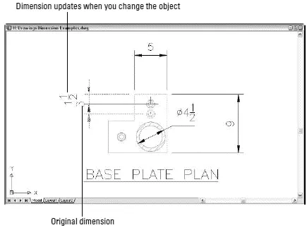
Figure 10-1:Changing objects automatically updates dimensions.
AutoCAD controls the look of dimensions by means of dimension styles , just as it controls the look of text with text styles. (AutoCAD also uses text styles to control the appearance of the text in dimensions.) But dimension styles are much more complicated than text styles, because dimensions have so many more pieces that you need to control. After you find or create an appropriate dimension style, you use one of several dimensioning commands to draw dimensions that point to the important points on an object (the two endpoints of a line, for example).
 AutoCAD dimensioning is a big, complicated subject. (It’s so complicated, in fact, that Autodesk has an especially wise person in charge of dimensioning in AutoCAD — this person is called the “DimWit.”) Every industry has its own dimensioning conventions, habits, and quirks. As usual, AutoCAD tries to support them all and, in so doing, makes things a bit convoluted for everyone. This chapter covers the essential concepts and commands that you need to know to start drawing dimensions. Be prepared to spend some additional time studying how to create any specialized types of dimensions that your industry uses.
 You may be able to avoid getting too deeply into the details of dimensioning just by copying dimension styles from existing drawings in your office. (I show you how later in this chapter.) This may also be a good time to get some advice and coaching from the AutoCAD geek in the cubicle across from yours.
 You add dimensions to a drawing after you’ve drawn at least some of the geometry; otherwise, you won’t have much to dimension! Your dimensioning and overall drafting efficiency improve if you add dimensions in batches, rather than draw a line, draw a dimension, draw another line, draw another dimension…
You may think that CAD would have rendered text dimensions obsolete. After all, you comply with all my suggestions about using AutoCAD precision techniques when you draw and edit, and you’re careful to draw each object at its true size, right? The contractor or machinist can just use AutoCAD to query distances and angles in the CAD DWG file, right? Sorry, but no (to the last question, anyway). Here are a few reasons why the traditional dimensioning that CAD drafting has inherited from manual drafting is likely to be around for a while:
□ Some people need to or want to use paper drawings when they build something.We’re still some time away from the day when contractors haul computers around in their tool belts (never mind mousing around a drawing while hanging from scaffolding).
□ In many industries, paper drawings still rule legally.Your company may supply both plotted drawings and DWG files to clients, but your contracts probably specify that the plotted drawings govern in the case of any discrepancy. The contracts probably also warn against relying on any distances that the recipient of the drawings measures — using measuring commands in the CAD DWG file or a scale on the plotted drawing. The text dimensions are supposed to supply all the dimensional information that’s needed to construct the object.
□ Dimensions sometimes carry additional information besides the basic length or angle.For example, dimension text can indicate the allowable construction tolerances or show that a particular distance is typical of similar situations elsewhere on the drawing.
□ Even conscientious CAD drafters rarely draw every object its true size.Drafters sometimes exaggerate distances for graphical clarity. For example, they might draw a small object larger than its true size so that it shows up clearly on a scaled plot. In addition, drafters sometimes settle for approximate distances because time pressures (especially late in a project) make it difficult to be completely accurate.
So remember the old rule of drafting prowess: “It’s not the size of the drawn object that matters, but the dimensions that are on it.”
Discovering New Dimensions
Before digging into the techniques that you use to create dimension styles and dimensions, I review some AutoCAD dimensioning terminology. If you’re already familiar with CAD dimensioning lingo, just skim this section and look at the figures in it. Otherwise, read on.
AutoCAD uses the names shown in Figure 10-2 and described in the following list to refer to the parts of each dimension:
□ Dimension text:Dimension text usually is the number that indicates the actual distance or angle. Dimension text can also include other text information in addition to or instead of the number. For example, you can add a suffix such as TYP. to indicate that a dimension is typical of several similar configurations, or you can insert a description such as See Detail 3/A2.
□ Dimension lines:The dimension lines go from the dimension text outward (parallel to the direction of the object being measured), to indicate the extent of the dimensioned length. AutoCAD’s default dimension style settings center the dimension text vertically and horizontally on the dimension lines (see Figure 10-2), but you can change those settings to cause the text to appear in a different location — riding above an unbroken dimension line as shown in Figure 10-1, for example. See the section “Adjusting style settings,” later in this chapter, for instructions.
□ Dimension arrowheads:
The dimension arrowheads appear at the ends of the dimension lines and clarify the extent of the dimensioned length. AutoCAD’s default arrowhead style is the closed, filled type shown in Figure 10-2, but you can choose other symbols, such as tick marks, to indicate the ends of the dimension lines. (Don’t get ticked off, but AutoCAD calls the line ending an arrowhead even when, as in the case of a tick mark, it doesn’t look like an arrow.)
□ Extension lines:The extension lines extend outward from the extension line origin points that you select (usually by snapping to points on an object) to the dimension lines. By drafting convention, a small gap usually exists between the extension line origin points and the beginning of the extension lines. The extension lines usually extend just beyond where they meet the dimension lines.
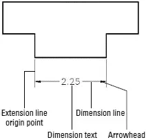
Figure 10-2:The parts of a dimension.
AutoCAD provides several types of dimensions and commands for drawing them. Figure 10-3 shows the most common types, and the following list describes them:
□ Linear dimensions:A linear dimension measures the linear extent of an object or the linear distance between objects. Most linear dimensions are either horizontal or vertical, but you can draw dimensions that are rotated to other angles, too. An aligned dimension is similar to a linear dimension, but the dimension line tilts to the same angle as a line drawn through the origin points of its extension lines.
Читать дальшеИнтервал:
Закладка:
Похожие книги на «AutoCAD 2005 for Dummies»
Представляем Вашему вниманию похожие книги на «AutoCAD 2005 for Dummies» списком для выбора. Мы отобрали схожую по названию и смыслу литературу в надежде предоставить читателям больше вариантов отыскать новые, интересные, ещё непрочитанные произведения.


Обсуждение, отзывы о книге «AutoCAD 2005 for Dummies» и просто собственные мнения читателей. Оставьте ваши комментарии, напишите, что Вы думаете о произведении, его смысле или главных героях. Укажите что конкретно понравилось, а что нет, и почему Вы так считаете.