Mark Middlebrook - AutoCAD 2005 for Dummies
Здесь есть возможность читать онлайн «Mark Middlebrook - AutoCAD 2005 for Dummies» — ознакомительный отрывок электронной книги совершенно бесплатно, а после прочтения отрывка купить полную версию. В некоторых случаях можно слушать аудио, скачать через торрент в формате fb2 и присутствует краткое содержание. Город: Indianapolis, Год выпуска: 2004, ISBN: 2004, Издательство: Wiley Publishing, Inc, Жанр: Программы, на английском языке. Описание произведения, (предисловие) а так же отзывы посетителей доступны на портале библиотеки ЛибКат.

- Название:AutoCAD 2005 for Dummies
- Автор:
- Издательство:Wiley Publishing, Inc
- Жанр:
- Год:2004
- Город:Indianapolis
- ISBN:0-7645-7138-9
- Рейтинг книги:5 / 5. Голосов: 1
-
Избранное:Добавить в избранное
- Отзывы:
-
Ваша оценка:
AutoCAD 2005 for Dummies: краткое содержание, описание и аннотация
Предлагаем к чтению аннотацию, описание, краткое содержание или предисловие (зависит от того, что написал сам автор книги «AutoCAD 2005 for Dummies»). Если вы не нашли необходимую информацию о книге — напишите в комментариях, мы постараемся отыскать её.
AutoCAD is more than just another application program, it’s a complete environment for drafting and design. So if you’re new to AutoCAD, you need to know several things to get off to a good start — especially how to use the command line area and set up your drawing properly. These key techniques are described in this part of the book.
If you’ve used earlier versions of AutoCAD, you’ll be most interested in the high points of the new release, including some newer interface components. The lowdown on what’s new is here, too.
AutoCAD 2005 for Dummies — читать онлайн ознакомительный отрывок
Ниже представлен текст книги, разбитый по страницам. Система сохранения места последней прочитанной страницы, позволяет с удобством читать онлайн бесплатно книгу «AutoCAD 2005 for Dummies», без необходимости каждый раз заново искать на чём Вы остановились. Поставьте закладку, и сможете в любой момент перейти на страницу, на которой закончили чтение.
Интервал:
Закладка:
4. Choose an Insertion Behavior.
Specify Insertion Point is the easiest method and means that you’ll pick the location of the table’s upper-left corner (or lower-left corner if you set Table Direction to Up in the table style). With this method, you specify the default column width and number of rows in the Insert Table dialog box.
Specify Window means that you’ll pick the upper-left corner and then the lower-right corner. With this method, AutoCAD automatically scales the column widths and determines how many rows to include.
5. Specify Column Row Settings.
If you chose Specify Window in Step 4, AutoCAD sets the Column Width and number of Data Rows to Auto, which means that AutoCAD will figure them out based on the overall size of the table that you specify in Steps 7 and 8.
6. Click OK.
AutoCAD prompts you to specify the insertion point of the table.
7. Click a point or type coordinates.
If you chose Specify Insertion Point in Step 4, AutoCAD draws the table grid lines, places the cursor in the title cell, and displays the Text Formatting toolbar.
8. If you chose Specify Window in Step 4, specify the diagonally opposite corner of the table.
AutoCAD draws the table. Based on the table size that you indicated, AutoCAD chooses the column width and number of rows.
9. Type a title for the table.
10. Press the arrow keys or tab key to move among cells, and type values in each cell.
The cell right-click menu offers many other options, including copying contents from one cell to another, merging cells, inserting rows and columns, changing formatting, and inserting a block (that is, a graphical symbol — see Chapter 13 for information about blocks).
 The new AutoCAD 2005 fields feature described earlier in this chapter works for table text, too — you can insert a field into a table cell. For example, you might use this feature to create part of a title block, with fields serving as the “date” and “drawn by” data.
11. Click OK on the Text Formatting toolbar.
Figure 9-8 shows a completed table, along with the Insert Table dialog box. You can edit cell values later simply by double-clicking in a cell. To change column width or row height, click on the table grid and then click and move the blue grips. (To change the width of one column without altering the overall width of the table, hold down the Ctrl key while you move the grip.) If you want to change other aspects of a table or individual cells in it, select the table or cell and use the Properties palette to make changes.
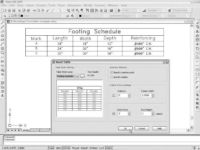
Figure 9-8:The Insert Table dialog box, and the result of using it.
 You can import tables from Microsoft Excel instead of using the Insert Table dialog box. To import Excel data, select the desired cells and choose Edit→Copy in Excel. Then in AutoCAD, choose Edit→Paste Special and choose AutoCAD Entities in the Paste Special dialog box. AutoCAD attempts to copy the Excel spreadsheet’s formatting along with the cell data, but you’ll probably have to adjust column widths and perform other cleanup on the imported table.
You can go the other direction — from AutoCAD to Excel or another program — via a CSV (Comma Separated Value) file. Look up “TABLEEXPORT command” in AutoCAD’s online help.
Checking Out Your Spelling
AutoCAD, like almost every other computer program on this planet — and possibly on other planets and moons in our solar system — has a spelling checker.
Unlike Microsoft Word, AutoCAD’s spelling checker doesn’t make those little red squiggles under your errors, but it does let you search for spelling errors in most of the text objects in your drawing. This feature checks single-line text, paragraph text, and attribute text (described in Chapter 13), but not dimension text (described in Chapter 10). The following procedure demonstrates how to use the spell checker:
1. Press the Esc key to unselect any selected objects.
2. Choose Tools→ Spelling to start the SPell command.
This is text spell-checking, not casting a spell. (That’s the EYEOFNEWT command.) The command line prompts you to select objects.
3. Select the objects you want to check.
You can use any of the standard AutoCAD object selection methods to select text to check. (See Chapter 6 if you’re unfamiliar with object selection.) Type ALLand press Enter if you want to check the spelling of all text in the drawing. Don’t worry if you select objects other than text; the spelling checker ignores any objects that aren’t text. When you’re finished selecting objects, press Enter to start the spelling check. If a misspelling is found, the Check Spelling dialog box appears with the first misspelled or unrecognized word. Figure 9-9 shows an example.
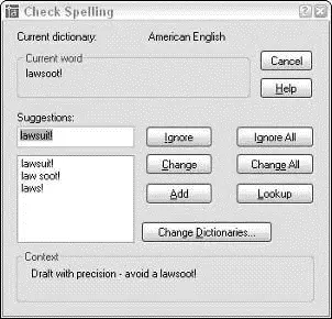
Figure 9-9:It’s good to sue your spelling checker.
4. Click the dialog box buttons to tell AutoCAD how to handle a misspelling.
You probably know which buttons to click from having used other spelling checkers. If not, use the dialog box help to find out: Click the question mark on the Check Spelling dialog box’s title bar, and then click the button that you want to know more about.
AutoCAD continues with spell-checking until it has checked all the selected text objects. When it finds no further misspellings, the dialog box disappears, and the Spelling check completealert appears.
Every industry has its own abbreviations and specialized vocabulary. At first, AutoCAD complains about perfectly good words (from a drafter’s point of view) such as thru and S.A.D. (which stands for See Architectural Drawing). Be prepared to click the Add button frequently during the first few weeks to tell AutoCAD which words and abbreviations are acceptable in your industry and office. If you’re patient with it, AutoCAD, like an errant puppy, will gradually become more obedient. Then you’ll be thru feeling S.A.D.
Chapter 10
Entering New Dimensions
□ Understanding dimension parts and types
□ Using dimension styles from other drawings
□ Creating and modifying your own dimension styles
□ Drawing dimensions
□ Editing dimensions
□ Drawing leaders
In drafting — either CAD or manual drafting — dimensions are special text labels with attached lines that together indicate unambiguously the size of something. Although it’s theoretically possible to draw all the pieces of each dimension by using AutoCAD commands such as Line and mText, dimensioning is so common a drafting task that AutoCAD provides special commands for doing the job more efficiently. These dimensioning commands group the parts of each dimension into a convenient, easy-to-edit package. Even better, as you edit an object — by stretching it for example — AutoCAD automatically updates the measurement displayed in the dimension text label to indicate the object’s new size, as shown in Figure 10-1.
Читать дальшеИнтервал:
Закладка:
Похожие книги на «AutoCAD 2005 for Dummies»
Представляем Вашему вниманию похожие книги на «AutoCAD 2005 for Dummies» списком для выбора. Мы отобрали схожую по названию и смыслу литературу в надежде предоставить читателям больше вариантов отыскать новые, интересные, ещё непрочитанные произведения.


Обсуждение, отзывы о книге «AutoCAD 2005 for Dummies» и просто собственные мнения читателей. Оставьте ваши комментарии, напишите, что Вы думаете о произведении, его смысле или главных героях. Укажите что конкретно понравилось, а что нет, и почему Вы так считаете.