Mark Middlebrook - AutoCAD 2005 for Dummies
Здесь есть возможность читать онлайн «Mark Middlebrook - AutoCAD 2005 for Dummies» — ознакомительный отрывок электронной книги совершенно бесплатно, а после прочтения отрывка купить полную версию. В некоторых случаях можно слушать аудио, скачать через торрент в формате fb2 и присутствует краткое содержание. Город: Indianapolis, Год выпуска: 2004, ISBN: 2004, Издательство: Wiley Publishing, Inc, Жанр: Программы, на английском языке. Описание произведения, (предисловие) а так же отзывы посетителей доступны на портале библиотеки ЛибКат.

- Название:AutoCAD 2005 for Dummies
- Автор:
- Издательство:Wiley Publishing, Inc
- Жанр:
- Год:2004
- Город:Indianapolis
- ISBN:0-7645-7138-9
- Рейтинг книги:5 / 5. Голосов: 1
-
Избранное:Добавить в избранное
- Отзывы:
-
Ваша оценка:
AutoCAD 2005 for Dummies: краткое содержание, описание и аннотация
Предлагаем к чтению аннотацию, описание, краткое содержание или предисловие (зависит от того, что написал сам автор книги «AutoCAD 2005 for Dummies»). Если вы не нашли необходимую информацию о книге — напишите в комментариях, мы постараемся отыскать её.
AutoCAD is more than just another application program, it’s a complete environment for drafting and design. So if you’re new to AutoCAD, you need to know several things to get off to a good start — especially how to use the command line area and set up your drawing properly. These key techniques are described in this part of the book.
If you’ve used earlier versions of AutoCAD, you’ll be most interested in the high points of the new release, including some newer interface components. The lowdown on what’s new is here, too.
AutoCAD 2005 for Dummies — читать онлайн ознакомительный отрывок
Ниже представлен текст книги, разбитый по страницам. Система сохранения места последней прочитанной страницы, позволяет с удобством читать онлайн бесплатно книгу «AutoCAD 2005 for Dummies», без необходимости каждый раз заново искать на чём Вы остановились. Поставьте закладку, и сможете в любой момент перейти на страницу, на которой закончили чтение.
Интервал:
Закладка:
One way to create a surface model is to extrude, or thicken, 2D objects. For example, if you give thickness to a circle, it becomes a cylinder. If you give thickness to a 2D polyline or a series of lines segments, it looks like a fence. AutoCAD calls this depth thickness, which is not to be confused with other characteristics that you may be tempted to call “thickness” — linewidths that you add for plotting and uniform or tapered widths that you can add to polyline segments. Linewidths and polyline segment widths make objects fatter but leave them in the 2D plane. Thickness pushes objects out of the plane, giving them a new dimension.
 Folks who do heavy-duty 3D modeling somewhat derisively refer to the result of adding thickness to 2D objects as 2½ D — a bit more than 2D, but not quite 3D. That’s because extrusion is a limited 3D technique compared to creating real surface meshes and solids, as described in the following two sections. You can’t model most objects in a detailed way with extrusion alone. Imagine a set of wooden blocks in which every block has a uniform thickness, with no tapering allowed — kind of dull, huh? Even AutoCAD LT, despite its advertised 3D limitations, can do extrusion (although only the simple kind of extrusion described in the following steps). Nonetheless, extrusion is a fun and fairly low-stress way to get started with 3D, and it’s adequate for some simple modeling tasks. It’s also a good warm-up exercise for full 3D solid extrusion, which I describe later in this chapter.
The following steps show the general procedure for creating “2½D” extruded objects.
1. Define a suitable UCS (user coordinate system), as described earlier in “Coordinate systems: The WCS and UCSs.”
The extrusion direction will be perpendicular to the UCS, so think about the orientation of the 2D object and which way you want it to “pop out” into 3D space.
2. Draw a 2D object.
See Chapter 5 for more information.
3. Open the Properties palette.
See Chapter 6 for more information.
4. Press Esc to make sure that no objects are selected.
5. Click the object to select it.
6. In the Thickness field, type an extrusion thickness and press Enter.
AutoCAD extrudes the object perpendicular to the UCS in which you created it, as shown in Figure 8-8.
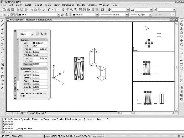
Figure 8-8:Just add thickness and voilà — instant 3D! (Or 2½D, anyway.)
 If you extrude closed polylines and then shade or render them, the extruded shapes appear hollow — that is, without any tops or bottoms on them. You can work around this limitation by using the 3DFACE command to add threesided or four-sided surfaces as “lids.” You can build up irregular shapes by using a combination of three-sided and four-sided faces. A better approach in most cases is to use the EXTrude command, which creates a true solid out of closed polylines and other closed shapes. (EXTrude requires AutoCAD — it’s not included in AutoCAD LT.)
For surface models that are more complex than simple extrusions of 2D objects, you can use a variety of AutoCAD commands that draw 3D meshes. One set of commands draws surface model representations of 3D primitives: box, pyramid, wedge, dome, sphere, cone, torus, dish, and mesh. (In this case, the word primitive isn’t a pejorative. A 3D primitive is a relatively simple shape that can be used alone or as a subcomponent of a more complex 3D object.)
To create these objects, choose Draw→Surfaces→3D Surfaces, select a primitive shape from the image tile menu (shown in Figure 8-9), and follow the command line prompts. It’s like constructing your own set of wooden blocks, except that they don’t take up any space in your closet after you’re finished playing with them!
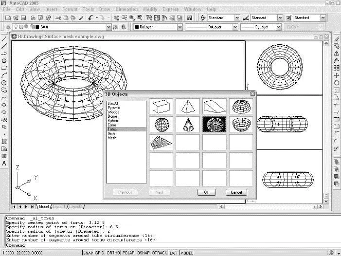
Figure 8-9:A torus mesh — the perfect 3D surface snack.
 The Surfaces submenu of the Draw menu includes commands for creating complex 3D surfaces from 2D lines and curves. For example, with the Revolved Surface menu choice (the REVSURF command), you revolve a set of 2D line and arc segments around an axis of revolution to “sweep out” a 3D surface. But in most cases, you’re better off using solid modeling commands such as REVolve instead.
Solid modeling is in many ways the culmination of 3D CAD. Solids more accurately represent most real-world objects than do wireframes or surfaces. And even when representational accuracy isn’t the main issue, it’s easier to construct many kinds of models with solids.
Solid modeling also places more serious demands on computer software and hardware. It takes a sophisticated program and fast computer — not to mention a capable human being running all this stuff — to create useful solid models. That’s why solid modeling historically has lagged behind wireframe and surface modeling and only recently become common on ordinary PCs. AutoCAD’s solid modeling capabilities have improved steadily over the years, but most people who do real solid modeling use AutoCAD add-on applications or separate, stand-alone programs that have been created with this task in mind. Examples include Inventor from Autodesk and SolidWorks from SolidWorks Corporation.
 Many special-purpose solid modeling programs use a combination of solid and surface modeling techniques for maximum flexibility in constructing and editing 3D models. These kinds of programs — and solid modeling in general — are becoming especially popular in mechanical design.
Constructing the basic building blocks — or solid primitives — for a solid model in AutoCAD isn’t difficult. As with wireframe and surface objects, you follow these steps:
1. Define a suitable UCS (user coordinate system).
See “Coordinate systems: The WCS and UCSs,” earlier in this chapter. The UCS controls the construction plane and basic 3D orientation of the solid.
2. Choose Draw→ Solids and then choose a solid from the top half of the submenu.
As shown in Figure 8-10, your choices are Box, Sphere, Cylinder, Cone, Wedge, and Torus. (These are similar to the surface mesh choices shown in Figure 8-9. In this case, though, you’re creating solid instead of surface versions.)
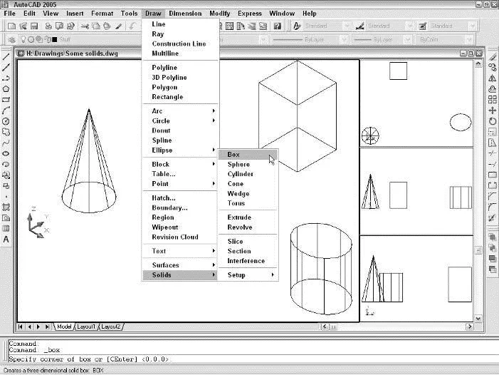
Figure 8-10:Everything you need for a solid foundation.
When you see a 3D object in a drawing, you can’t tell by looking whether it’s a 2D extruded object, surface mesh, or solid. If you want to find out, open the Properties palette and select the object. The drop-down list at the top of the palette shows the type of object that you selected.
Интервал:
Закладка:
Похожие книги на «AutoCAD 2005 for Dummies»
Представляем Вашему вниманию похожие книги на «AutoCAD 2005 for Dummies» списком для выбора. Мы отобрали схожую по названию и смыслу литературу в надежде предоставить читателям больше вариантов отыскать новые, интересные, ещё непрочитанные произведения.


Обсуждение, отзывы о книге «AutoCAD 2005 for Dummies» и просто собственные мнения читателей. Оставьте ваши комментарии, напишите, что Вы думаете о произведении, его смысле или главных героях. Укажите что конкретно понравилось, а что нет, и почему Вы так считаете.