Mark Middlebrook - AutoCAD 2005 for Dummies
Здесь есть возможность читать онлайн «Mark Middlebrook - AutoCAD 2005 for Dummies» — ознакомительный отрывок электронной книги совершенно бесплатно, а после прочтения отрывка купить полную версию. В некоторых случаях можно слушать аудио, скачать через торрент в формате fb2 и присутствует краткое содержание. Город: Indianapolis, Год выпуска: 2004, ISBN: 2004, Издательство: Wiley Publishing, Inc, Жанр: Программы, на английском языке. Описание произведения, (предисловие) а так же отзывы посетителей доступны на портале библиотеки ЛибКат.

- Название:AutoCAD 2005 for Dummies
- Автор:
- Издательство:Wiley Publishing, Inc
- Жанр:
- Год:2004
- Город:Indianapolis
- ISBN:0-7645-7138-9
- Рейтинг книги:5 / 5. Голосов: 1
-
Избранное:Добавить в избранное
- Отзывы:
-
Ваша оценка:
AutoCAD 2005 for Dummies: краткое содержание, описание и аннотация
Предлагаем к чтению аннотацию, описание, краткое содержание или предисловие (зависит от того, что написал сам автор книги «AutoCAD 2005 for Dummies»). Если вы не нашли необходимую информацию о книге — напишите в комментариях, мы постараемся отыскать её.
AutoCAD is more than just another application program, it’s a complete environment for drafting and design. So if you’re new to AutoCAD, you need to know several things to get off to a good start — especially how to use the command line area and set up your drawing properly. These key techniques are described in this part of the book.
If you’ve used earlier versions of AutoCAD, you’ll be most interested in the high points of the new release, including some newer interface components. The lowdown on what’s new is here, too.
AutoCAD 2005 for Dummies — читать онлайн ознакомительный отрывок
Ниже представлен текст книги, разбитый по страницам. Система сохранения места последней прочитанной страницы, позволяет с удобством читать онлайн бесплатно книгу «AutoCAD 2005 for Dummies», без необходимости каждый раз заново искать на чём Вы остановились. Поставьте закладку, и сможете в любой момент перейти на страницу, на которой закончили чтение.
Интервал:
Закладка:
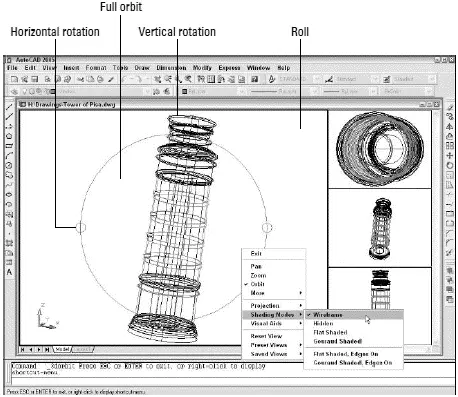
Figure 8-4:The 3DOrbit arcball and right-click menu.
3. Move the cursor inside the arcball.
The 3DOrbit full orbit cursor appears: two oval arrows circling a sphere.
4. Click and drag, keeping the cursor inside the arcball.
You can rotate the model in all directions. Imagine that the cursor is your finger pushing on a globe that rotates freely in all directions.
 Pay attention to the shaded UCS (user coordinate system) icon at the lower-left corner of the drawing area as you change the view. The UCS icon helps you visualize how each orbiting operation works. (The next section of this chapter tells more about UCSs.)
5. Release the mouse button and move the cursor outside the arcball.
The 3DOrbit roll cursor appears: a circular arrow circling a sphere.
6. Click and drag, keeping the cursor outside the arcball.
You can rotate the model around an axis at the center of the circle, coming out of the screen. Imagine that you’re turning the steering wheel on a car, with the steering column pointing into the screen.
7. Release the mouse button and move the cursor over one of the small circles at the quadrant points (that is, 12 o’clock, 3 o’clock, 6 o’clock, and 9 o’clock) of the arcball.
The 3DOrbit horizontal or vertical rotation cursor appears: an elliptical arrow circling a sphere.
8. Click and drag away from the small circle.
You can rotate the model around a horizontal axis (if you clicked the circle at 3 o’clock or 9 o’clock) or a vertical axis (if you clicked the circle at 12 o’clock or 6 o’clock) passing through the little circle. Imagine that you’re turning a piece of meat on a spit, with the spit located horizontally or vertically in the plane of the screen.
9. Release the mouse button and right-click in the drawing area.
The 3DOrbit shortcut menu, shown in Figure 8-4, appears.
10. Experiment with the additional options, such as Shading Modes and Projection.
Here’s the lowdown on some of these options:
• Gouraud Shaded usually looks more realistic than Flat Shaded.
• Hidden removes hidden lines but doesn’t shade.
• Wireframe is the default wireframe view, without hidden lines removed.
• Parallel projection is the default AutoCAD projection — lines that are parallel in the 3D object remain parallel in the projected view on the screen.
• Perspective projection makes objects look more realistic (for example, train tracks appear to converge in the distance), but lines that are parallel in the model don’t remain parallel in perspective projection.
If you manage to 3DOrbit out of control so that you no longer see your model, right-click to display the 3DOrbit shortcut menu and choose More→Zoom Extents. The Zoom, Pan, and Preset Views options offer other ways of getting your model back in your sights.
11. When you’re finished orbiting, right-click in the drawing area and choose Exit.
Choose More→Adjust Clipping Planes on the 3DOrbit right-click menu (or the 3DCLIP command outside of 3DOrbit) to slice away part of your model temporarily to view what’s inside the surfaces or solid boundaries. See “clipping, 3D objects” in the AutoCAD online help for more information.
 You can control the camera point and target point that 3DOrbit uses (the point that you’re looking from and the point that you’re looking towards). Before you start the 3DOrbit command, type CAMERAat the command prompt and press Enter. Click or type the coordinates of the desired camera point target points.
A Cartesian Orientation
Viewing your model from different viewpoints in multiple viewports is all well and good, but unless your 3D spree is limited to looking at other people’s models, you need to know how to specify points and distances in 3D. To do that, you need to understand AutoCAD’s coordinate systems and conventions for entering 3D points and distances.
AutoCAD stores the locations of all the objects that you draw as 3D Cartesian coordinates (X, Y, and Z) in the world coordinate system (or WCS). The WCS defines the origin (0,0,0) point for the drawing and the orientation of the X, Y, and Z axes. A particular point in the Cartesian coordinate system is defined by its X, Y, and Z coordinates, where the coordinate indicates the distance from the origin (0,0,0) point along the X, Y, or Z axis.
The WCS is the default XYZ coordinate system when you start a new drawing. X is horizontal on the screen, Y is vertical on the screen, and Z extends out of the screen, towards your face.
The X-Y plane (the set of points where Z=0) is the construction plane in which you create 2D objects. It’s also important for creating 3D objects, because many commands operate with respect to the X-Y plane.
When you’re drawing and editing 3D objects, it’s often useful to be able to move or rotate the construction plane. You do so in AutoCAD by defining a user coordinate system (UCS). A UCS can have a different origin (0,0,0) point and can have its X, Y, and Z axes point in different directions than they do in the WCS.
Choose Tools→Orthographic UCS→Preset to run the UCSMAN command, which opens the UCS dialog box, shown in Figure 8-5. This dialog box simplifies the job of changing to common UCSs, such as Top, Front, and Right. The Tools→New UCS submenu runs the UCS command, which provides additional options. Look up “UCS command” in AutoCAD’s online help to find out more about UCSs and how to work with them.
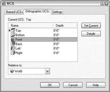
Figure 8-5:Get with the UCSMAN.
To keep you informed about which coordinate system is current in each viewport, AutoCAD displays a UCS (user coordinate system) icon in each viewport by default. The icon looks like two or three little arrows (depending on the viewpoint), each of which represents the direction of the positive X, Y, or Z axis. This icon shows the working construction plane — the plane in which AutoCAD places 2D objects when you draw them. Use the View→Display→UCS Icon submenu to turn the icon off or on or to change its properties.
 Don’t confuse viewpoints and coordinate systems:
□ The viewpoint controls what you see in a particular viewport, but doesn’t control what you do to objects — that is, the viewpoint doesn’t dictate the results of drawing and editing commands.
□ The current coordinate system defines the construction plane in a particular viewport — that is, the UCS (or WCS) dictates how the points that you specify during drawing and editing commands influence the specific locations and orientations of objects. The UCS icon shows the current coordinate system, not the current viewpoint.
Читать дальшеИнтервал:
Закладка:
Похожие книги на «AutoCAD 2005 for Dummies»
Представляем Вашему вниманию похожие книги на «AutoCAD 2005 for Dummies» списком для выбора. Мы отобрали схожую по названию и смыслу литературу в надежде предоставить читателям больше вариантов отыскать новые, интересные, ещё непрочитанные произведения.


Обсуждение, отзывы о книге «AutoCAD 2005 for Dummies» и просто собственные мнения читателей. Оставьте ваши комментарии, напишите, что Вы думаете о произведении, его смысле или главных героях. Укажите что конкретно понравилось, а что нет, и почему Вы так считаете.