Mark Middlebrook - AutoCAD 2005 for Dummies
Здесь есть возможность читать онлайн «Mark Middlebrook - AutoCAD 2005 for Dummies» — ознакомительный отрывок электронной книги совершенно бесплатно, а после прочтения отрывка купить полную версию. В некоторых случаях можно слушать аудио, скачать через торрент в формате fb2 и присутствует краткое содержание. Город: Indianapolis, Год выпуска: 2004, ISBN: 2004, Издательство: Wiley Publishing, Inc, Жанр: Программы, на английском языке. Описание произведения, (предисловие) а так же отзывы посетителей доступны на портале библиотеки ЛибКат.

- Название:AutoCAD 2005 for Dummies
- Автор:
- Издательство:Wiley Publishing, Inc
- Жанр:
- Год:2004
- Город:Indianapolis
- ISBN:0-7645-7138-9
- Рейтинг книги:5 / 5. Голосов: 1
-
Избранное:Добавить в избранное
- Отзывы:
-
Ваша оценка:
AutoCAD 2005 for Dummies: краткое содержание, описание и аннотация
Предлагаем к чтению аннотацию, описание, краткое содержание или предисловие (зависит от того, что написал сам автор книги «AutoCAD 2005 for Dummies»). Если вы не нашли необходимую информацию о книге — напишите в комментариях, мы постараемся отыскать её.
AutoCAD is more than just another application program, it’s a complete environment for drafting and design. So if you’re new to AutoCAD, you need to know several things to get off to a good start — especially how to use the command line area and set up your drawing properly. These key techniques are described in this part of the book.
If you’ve used earlier versions of AutoCAD, you’ll be most interested in the high points of the new release, including some newer interface components. The lowdown on what’s new is here, too.
AutoCAD 2005 for Dummies — читать онлайн ознакомительный отрывок
Ниже представлен текст книги, разбитый по страницам. Система сохранения места последней прочитанной страницы, позволяет с удобством читать онлайн бесплатно книгу «AutoCAD 2005 for Dummies», без необходимости каждый раз заново искать на чём Вы остановились. Поставьте закладку, и сможете в любой момент перейти на страницу, на которой закончили чтение.
Интервал:
Закладка:
As I indicate in Chapter 4, you specify points in 2D drafting by typing a pair of numbers in the format X,Y for absolute coordinates (with respect to the point 0,0) or @X,Y for relative coordinates (with respect to the previous point that you specified). In both cases, you ignore the Z coordinate, but AutoCAD still stores it — as zero.
When you create 3D models, you no longer can ignore the Z axis. You need to worry about three coordinates for each point that you pick or type. AutoCAD provides several ways of specifying 3D points. These are the most common:
□ Typed coordinates:When you type coordinates, you simply add a Z coordinate: X,Y,Z for absolute coordinates (with respect to the point 0,0,0) or @X,Y,Z for relative coordinates.
 There are 3D analogues to 2D polar coordinates (@ distance ), too. See “polar coordinates, entering, cylindrical” and “polar coordinates, entering, spherical” in the AutoCAD online help.
□ Object snaps:Happily, the object snap techniques described in Chapter 4 for picking precise locations on existing objects work equally well in 3D. You can object snap to endpoints, intersections, midpoints, and so on, without having to worry about the current construction plane as defined by the WCS or UCS.
 In practice, you’ll have to be more careful when using object snaps in 3D work. Remember that there are now three coordinates instead of two to be precise about. If you’re viewing a 3D model from just one viewpoint, it’s easy to osnap to a point that looks right in that view but in fact lies “deeper” or “shallower” in 3D space that you realize. Thus it’s a good idea to display your model from several different points of view, as described in the “Getting Your 3D Bearings” section, earlier in this chapter. The different points of view help you predict which location in 3D space a given object snap mode will grab and make any object snap mistakes more obvious.
An additional object snap mode, Apparent Intersection, is useful when you want to snap to the imaginary intersection of two objects that appear on the screen to intersect, but don’t in fact intersect because they lie in different planes.
□ Coordinate filters:You’ll sometimes need to pick a point some of whose coordinates (for example, the X and Y coordinates) match one object snap point and some of whose coordinates (for example, the Z coordinate) match another object snap point. Coordinate filters — also called point filters — solve this problem handily. With coordinate filters, you use the coordinates of points on existing objects to help specify new points. You use coordinate filters together with object snaps to “build up” a point one or two coordinates at a time. When AutoCAD prompts you to pick a point, you activate a coordinate filter before you pick the point. The coordinate filter tells AutoCAD which coordinates of the subsequent point to use.
You activate a coordinate filter by clicking one of the six choices on the object snap cursor menu’s Point Filters submenu (shown in Figure 8-6): .X, .Y, .Z, .XY, .YZ, or .XZ. (You display the object snap cursor menu by pressing Shift+right-click; see Chapter 4 for more information.) For example, if you select .XY and then pick a point, AutoCAD remembers only the X and Y coordinates of that point. AutoCAD then prompts you to pick another point and combines the Z coordinate of that second point with the X and Y coordinates of the first point to determine the 3D location of the new point. Look up “coordinate filters” in AutoCAD’s online help for more information and an example.
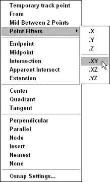
Figure 8-6:The object snap cursor menu’s Point Filters submenu.
At this point, you may be feeling less then completely 3D-coordinated, despite the WCS, UCSs, and XYZs. All this stuff will become clearer after you create some viewports and draw some objects. The next section gives you some specific instructions, but don’t be afraid to experiment with typing Cartesian coordinates, object snapping in 3D, and working with different predefined UCSs. Or, you can console yourself with the following paragraph’s geometrical trivia and vile pun.
In case you’re wondering, the Cartesian coordinate system is named after its inventor, the French mathematician René Descartes. (Yes, he of “I think therefore I am” and the Monty Python Philosophers’ Drinking Song fame.) He did not, however, invent the cart. The cart came earlier, and the horse came earlier still. It’s for that reason that we know not to put Descartes before de horse.
Drawing in 3D
This section introduces four techniques for creating 3D objects: drawing 3D lines and polylines, extruding 2D objects, creating surface meshes, and creating solids.
 When you draw 3D objects, just like when you draw 2D objects, put them on appropriate layers and use precision techniques to specify each point and distance. See Chapter 4 for more information.
The most straightforward way to draw objects for a 3D wireframe model is to use the Line or 3DPOLY (3D Polyline) command and specify 3D coordinates. The 3DPOLY command is similar to the PLine (Polyline) command, which is described in Chapter 5. Both commands draw a series of connected line segments, but they have different capabilities:
□ The 3DPOLY command accepts 3D points for the line segments’ vertices. The PLine command requires that all vertices be in the same plane.
□ 3DPOLY is limited to straight line segments. PLine can draw arc segments and create segments with uniform or tapered width.
□ Segments created with 3DPOLY can’t display dash-dot linetypes; 3D polyline segments always display as continuous lines.
The command sequence for drawing 3D segments with the Line or 3DPOLY command is the same as for drawing 2D segments with the Line command; see Chapter 5 for details. The only difference is that you specify 3D coordinates instead of 2D ones. Figure 8-7 shows an example.
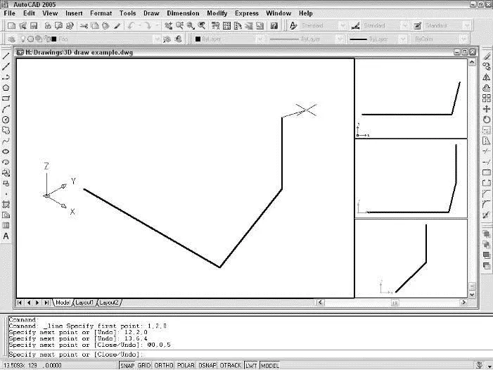
Figure 8-7:Drawing 3D line segments.
Creating 2D representations in this way is straightforward, though tedious for all but the simplest objects. More important, a wireframe model becomes increasingly difficult to decipher as the complexity of the model increases. You see a mass of lines representing the edges, and you have difficulty telling which parts of which edges are in front of others. To reduce this visual confusion, you need to graduate to a surface or solid modeling commands, as described earlier and in the subsequent sections of this chapter.
Читать дальшеИнтервал:
Закладка:
Похожие книги на «AutoCAD 2005 for Dummies»
Представляем Вашему вниманию похожие книги на «AutoCAD 2005 for Dummies» списком для выбора. Мы отобрали схожую по названию и смыслу литературу в надежде предоставить читателям больше вариантов отыскать новые, интересные, ещё непрочитанные произведения.


Обсуждение, отзывы о книге «AutoCAD 2005 for Dummies» и просто собственные мнения читателей. Оставьте ваши комментарии, напишите, что Вы думаете о произведении, его смысле или главных героях. Укажите что конкретно понравилось, а что нет, и почему Вы так считаете.