Mark Middlebrook - AutoCAD 2005 for Dummies
Здесь есть возможность читать онлайн «Mark Middlebrook - AutoCAD 2005 for Dummies» — ознакомительный отрывок электронной книги совершенно бесплатно, а после прочтения отрывка купить полную версию. В некоторых случаях можно слушать аудио, скачать через торрент в формате fb2 и присутствует краткое содержание. Город: Indianapolis, Год выпуска: 2004, ISBN: 2004, Издательство: Wiley Publishing, Inc, Жанр: Программы, на английском языке. Описание произведения, (предисловие) а так же отзывы посетителей доступны на портале библиотеки ЛибКат.

- Название:AutoCAD 2005 for Dummies
- Автор:
- Издательство:Wiley Publishing, Inc
- Жанр:
- Год:2004
- Город:Indianapolis
- ISBN:0-7645-7138-9
- Рейтинг книги:5 / 5. Голосов: 1
-
Избранное:Добавить в избранное
- Отзывы:
-
Ваша оценка:
AutoCAD 2005 for Dummies: краткое содержание, описание и аннотация
Предлагаем к чтению аннотацию, описание, краткое содержание или предисловие (зависит от того, что написал сам автор книги «AutoCAD 2005 for Dummies»). Если вы не нашли необходимую информацию о книге — напишите в комментариях, мы постараемся отыскать её.
AutoCAD is more than just another application program, it’s a complete environment for drafting and design. So if you’re new to AutoCAD, you need to know several things to get off to a good start — especially how to use the command line area and set up your drawing properly. These key techniques are described in this part of the book.
If you’ve used earlier versions of AutoCAD, you’ll be most interested in the high points of the new release, including some newer interface components. The lowdown on what’s new is here, too.
AutoCAD 2005 for Dummies — читать онлайн ознакомительный отрывок
Ниже представлен текст книги, разбитый по страницам. Система сохранения места последней прочитанной страницы, позволяет с удобством читать онлайн бесплатно книгу «AutoCAD 2005 for Dummies», без необходимости каждый раз заново искать на чём Вы остановились. Поставьте закладку, и сможете в любой момент перейти на страницу, на которой закончили чтение.
Интервал:
Закладка:
1. Click the Trim or Extend button on the Modify toolbar.
AutoCAD prompts you to select cutting edges that will do the trimming (or, if you chose the EXtend command, boundary edges for extending to):
Current settings: Projection=UCS, Edge=None
Select cutting edges ...
Select objects:
2. Select one or more objects that will act as the knife for trimming objects or the wall to which objects will be extended. Press Enter to end object selection.
Figure 6-12 shows a cutting edge (for TRim) and a boundary edge (for EXtend).
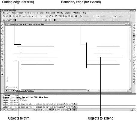
Figure 6-12:Anatomy of the TRim and EXtend operations.
AutoCAD prompts you to select objects that you want to trim or extend:
Select object to trim or shift-select to extend or
[Project/Edge/Undo]:
3. Select a single object to trim or extend. Choose the portion of the object that you want AutoCAD to trim away or the end of the object that’s closer to the extend-to boundary.
AutoCAD trims or extends the object to one of the objects that you selected in Step 2. If AutoCAD can’t trim or extend the object — for example, if the trimming object and the object to be trimmed are parallel — the command line displays an error message such as Object does not intersect an edge.
 TRim and EXtend normally allow you to select only one object at a time for trimming or extending. The one exception is that you can type Fand press Enter to use the Fence object selection mode (refer to Table 6-1). Fence is useful for trimming or extending a large group of objects in one fell swoop.
The command line continues to prompt you to select other objects to trim or extend:
Select object to trim or shift-select to extend or
[Project/Edge/Undo]:
4. Choose additional objects, or press Enter when you’re finished trimming or extending.
If you accidentally trim or extend the wrong object and you’re still in the TRim or EXtend command, type Uand press Enter to undo the most recent trim or extend.
The example in Figure 6-12 shows trimming to a single cutting edge, in which the end of the trimmed lines gets lopped off. Another common use of the TRim command is for trimming out a piece of a line between two cutting edges. In the two-cutting-edges scenario, TRim cuts a piece out of the middle of the trimmed line.
The LENgthen command provides other useful ways to make lines, arcs, and polylines longer (or shorter). You can specify an absolute distance (or “delta”) to lengthen or shorten by, a percentage to lengthen or shorten by, or a new total length. Look up “LENGTHEN command” in AutoCAD’s help system for more information.
The BReak command isn’t what you use before heading out for coffee. It’s for breaking pieces out of — that is, creating gaps in — lines, polylines, circles, arcs, or splines. BReak also comes in handy if you need to split one object into two without actually removing any visible material.
 If you want to create regularly spaced gaps in an object — so that it displays dashed, for instance — don’t use BReak. Use an AutoCAD dash-dot linetype instead. See Chapter 4 for more linetype information.
The following example shows how you BReak an object:
1. Click the Break button on the Modify toolbar.
AutoCAD prompts you to select a single object that you want to break:
Select object:
2. Select a single object, such as a line, polyline, or arc.
The point you pick when selecting the object serves double duty: It selects the object, of course, but it also becomes the default first break point (that is, it defines one side of the gap that you’ll create). Thus, you should either use one of the AutoCAD precision techniques, such as an object snap, to pick the object at a precise point, or use the First pointoption (described in the next step) to repick the first break point.
AutoCAD prompts you to specify the second break point, or to type Fand press Enter if you want to respecify the first break point:
Specify second break point or [First point]:
3. If the point that you picked in the preceding step doesn’t also correspond to a break point (see the previous tip), typeF and press Enter to respecify the first break point, and then pick the point with an object snap or other precision technique.
If you do type Fand press Enter and then respecify the first break point, AutoCAD prompts you now to select the second break point:
Specify second break point:
4. Specify the second break point by picking a point or typing coordinates.
AutoCAD cuts a section out of the object, using the first and second break points to define the length of the gap.
If you want to cut an object into two pieces without removing anything, click the Break at Point button on the Modify toolbar. You first select the object and then choose a second point that defines where AutoCAD breaks the object in two. You can then move, copy, or otherwise manipulate each section of the original object as a separate object.
Whereas TRim, EXtend, and BReak alter one object at a time, the Fillet and CHamfer commands require a pair of objects. As Figure 6-13 shows, Fillet creates a curved corner between two lines, whereas CHamfer creates an angled, straight corner. In case you wondered, it’s pronounced “fill-et,” not “fill-eh.” Saying that you know how to “fill-eh” may get you a job in a butcher shop, but it will get you strange looks in a design office.
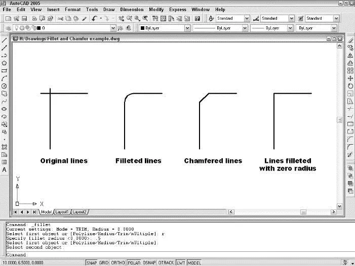
Figure 6-13:Cleaning up those corners with Fillet and CHamfer.
The following steps describe how to use the Fillet command:
1. Click the Fillet button on the Modify toolbar.
AutoCAD displays the current Fillet settings and prompts you to select the first object for filleting or specify one of three options:
Current settings: Mode = TRIM, Radius = 0.0000
Select first object or [Polyline/Radius/Trim/mUltiple]:
2. TypeR and press Enter to set the fillet radius.
Читать дальшеИнтервал:
Закладка:
Похожие книги на «AutoCAD 2005 for Dummies»
Представляем Вашему вниманию похожие книги на «AutoCAD 2005 for Dummies» списком для выбора. Мы отобрали схожую по названию и смыслу литературу в надежде предоставить читателям больше вариантов отыскать новые, интересные, ещё непрочитанные произведения.


Обсуждение, отзывы о книге «AutoCAD 2005 for Dummies» и просто собственные мнения читателей. Оставьте ваши комментарии, напишите, что Вы думаете о произведении, его смысле или главных героях. Укажите что конкретно понравилось, а что нет, и почему Вы так считаете.