Mark Middlebrook - AutoCAD 2005 for Dummies
Здесь есть возможность читать онлайн «Mark Middlebrook - AutoCAD 2005 for Dummies» — ознакомительный отрывок электронной книги совершенно бесплатно, а после прочтения отрывка купить полную версию. В некоторых случаях можно слушать аудио, скачать через торрент в формате fb2 и присутствует краткое содержание. Город: Indianapolis, Год выпуска: 2004, ISBN: 2004, Издательство: Wiley Publishing, Inc, Жанр: Программы, на английском языке. Описание произведения, (предисловие) а так же отзывы посетителей доступны на портале библиотеки ЛибКат.

- Название:AutoCAD 2005 for Dummies
- Автор:
- Издательство:Wiley Publishing, Inc
- Жанр:
- Год:2004
- Город:Indianapolis
- ISBN:0-7645-7138-9
- Рейтинг книги:5 / 5. Голосов: 1
-
Избранное:Добавить в избранное
- Отзывы:
-
Ваша оценка:
AutoCAD 2005 for Dummies: краткое содержание, описание и аннотация
Предлагаем к чтению аннотацию, описание, краткое содержание или предисловие (зависит от того, что написал сам автор книги «AutoCAD 2005 for Dummies»). Если вы не нашли необходимую информацию о книге — напишите в комментариях, мы постараемся отыскать её.
AutoCAD is more than just another application program, it’s a complete environment for drafting and design. So if you’re new to AutoCAD, you need to know several things to get off to a good start — especially how to use the command line area and set up your drawing properly. These key techniques are described in this part of the book.
If you’ve used earlier versions of AutoCAD, you’ll be most interested in the high points of the new release, including some newer interface components. The lowdown on what’s new is here, too.
AutoCAD 2005 for Dummies — читать онлайн ознакомительный отрывок
Ниже представлен текст книги, разбитый по страницам. Система сохранения места последней прочитанной страницы, позволяет с удобством читать онлайн бесплатно книгу «AutoCAD 2005 for Dummies», без необходимости каждый раз заново искать на чём Вы остановились. Поставьте закладку, и сможете в любой момент перейти на страницу, на которой закончили чтение.
Интервал:
Закладка:
2. Click the Scale button on the Modify toolbar.
3. Select one or more objects and then press Enter to end object selection.
AutoCAD prompts you for the base point about which it will scale all the selected objects:
Specify base point:
 AutoCAD does not scale each object individually around its own base point (because most AutoCAD drawing objects don’t have individual base points). Instead, AutoCAD uses the base point that you specify to determine how to scale all objects in the selection set. For example, if you select a circle to scale, pick a point outside the circle as the base point, and then specify a scale factor of 2, AutoCAD not only makes the circle twice as big, but also moves the circle twice as far away from the base point that you specified.
4. Specify a base point by picking a point or typing coordinates.
The base point becomes the point about which the objects are scaled. AutoCAD prompts you for the scale factor:
Specify scale factor or [Reference]:
5. Type a scale factor and press Enter.
AutoCAD then scales the objects by the factor that you type, using the base point that you specified. Numbers greater than one increase the objects’ size. Numbers smaller than one decrease the objects’ size.
 Changing the drawing scale factor of a drawing after you’ve drawn it is a tedious and complicated process in AutoCAD. In brief, you need to change the scale-dependent system variables described in Chapter 3, and then scale some, but not all, drawing objects. You don’t scale the real-world geometry that you’ve drawn, because its measurements in the real world remain the same. You do scale objects such as text and hatching that have a fixed height or spacing regardless of drawing scale factor. (The SCALETEXT command can help with this operation. See Chapter 9 for more information.) Because of these complications, try to make sure that you choose a proper scale and set up the drawing properly for that scale before you begin drawing. See Chapter 3 for details.
The ARray command is like a supercharged CoPy: You use it to create a rectangular grid of objects at regular X and Y spacings or a polar wheel of objects at a regular angular spacing. For example, you can use rectangular arrays to populate an auditorium with chairs or a polar array to draw bicycle spokes. The following steps describe how to create a rectangular array, which you’ll probably do more often than creating a polar array:
1. Press Esc to make sure that no command is active and no objects are selected.
Alternatively, you can select objects before starting the ARray command and thereby skip Step 3.
2. Click the Array button on the Modify toolbar.
The Array dialog box appears, as shown in Figure 6-10.
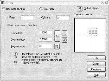
Figure 6-10:ARray makes duplicates of objects in a rectangular or polar pattern.
3. Click the Select Objects button, and then select one or more objects. Press Enter to end object selection and return to the Array dialog box.
4. Make sure that the Rectangular Array radio button is selected.
If rectangular arrays seem too square, choose the cool Polar Array radio button instead and experiment with the other array option.
5. Fill in the five edit boxes: Rows, Columns, Row Offset, Column Offset, and Angle of Array.
The Rows and Columns numbers include the row and column of the original objects themselves. In other words, entries of 1 don’t create any new objects in that direction. The Row Offset and Column Offset measurements are the distances between adjacent rows and columns.
6. Click Preview.
AutoCAD shows what the array will look like by using your current settings and displays a dialog box with Accept, Modify, and Cancel buttons.
7. Click the Accept button if you’re satisfied with the array, or the Modify button if you want to change the array parameters.
You use Offset to create parallel copies of lines, polylines, circles, arcs, or splines. Follow these steps to use OFfset:
1. Click the Offset button on the Modify toolbar.
AutoCAD prompts you for the offset distance — the distance from the original object to the copy you’re creating:
Specify offset distance or [Through] :
2. Type an offset distance and press Enter.
Alternatively, you can indicate an offset distance by picking two points on the screen. If you choose this method, you normally should use object snaps to specify a precise distance from one existing object to another.
AutoCAD prompts you to select the object from which you want to create an offset copy:
Select object to offset or :
3. Select a single object, such as a line, polyline, or arc.
Note that you can select only one object at a time with the OFfset command. AutoCAD asks where you want the offset object:
Specify point on side to offset:
4. Point to one side or the other of the object and then click.
It doesn’t matter how far away from the object the cursor is when you click. You’re simply indicating a direction.
AutoCAD repeats the Select objectprompt, in case you want to offset other objects by the same distance:
Select object to offset or :
5. Go back to Step 3 if you want to offset another object, or press Enter if you’re finished offsetting objects for now.
Figure 6-11 shows the OFfset command in progress.
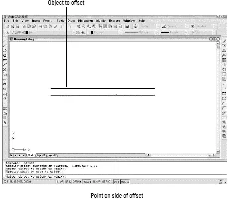
Figure 6-11:Offsetting a line.
 If you want to offset a series of connected lines (for example, a rectangular house plan outline or one side of a pathway on a map), make sure that you either draw it as a polyline or convert the individual line and/or arc segments into a polyline with the PEdit command. If you draw a series of line segments with the Line command and then try to offset it, you have to pick each segment and offset it individually. Even worse, the corners usually aren’t finished off in the way that you’d expect, because AutoCAD doesn’t treat the segments as connected. You avoid all these problems by offsetting a polyline, which AutoCAD does treat as a single object. See Chapter 5 for more information about the differences between lines and polylines.
The commands in this section — TRim, EXtend, BReak, Fillet, and CHamfer — are useful for shortening and lengthening objects and for breaking them in two.
TRim and EXtend are the twin commands for making lines, polylines, and arcs shorter and longer. They’re the yin and yang, the Laurel and Hardy, the Jack Sprat and his wife of the AutoCAD editing world. The two commands and their prompts are almost identical, so the following steps cover both. I show the prompts for the TRim command; the EXtend prompts are similar:
Читать дальшеИнтервал:
Закладка:
Похожие книги на «AutoCAD 2005 for Dummies»
Представляем Вашему вниманию похожие книги на «AutoCAD 2005 for Dummies» списком для выбора. Мы отобрали схожую по названию и смыслу литературу в надежде предоставить читателям больше вариантов отыскать новые, интересные, ещё непрочитанные произведения.


Обсуждение, отзывы о книге «AutoCAD 2005 for Dummies» и просто собственные мнения читателей. Оставьте ваши комментарии, напишите, что Вы думаете о произведении, его смысле или главных героях. Укажите что конкретно понравилось, а что нет, и почему Вы так считаете.