Mark Middlebrook - AutoCAD 2005 for Dummies
Здесь есть возможность читать онлайн «Mark Middlebrook - AutoCAD 2005 for Dummies» — ознакомительный отрывок электронной книги совершенно бесплатно, а после прочтения отрывка купить полную версию. В некоторых случаях можно слушать аудио, скачать через торрент в формате fb2 и присутствует краткое содержание. Город: Indianapolis, Год выпуска: 2004, ISBN: 2004, Издательство: Wiley Publishing, Inc, Жанр: Программы, на английском языке. Описание произведения, (предисловие) а так же отзывы посетителей доступны на портале библиотеки ЛибКат.

- Название:AutoCAD 2005 for Dummies
- Автор:
- Издательство:Wiley Publishing, Inc
- Жанр:
- Год:2004
- Город:Indianapolis
- ISBN:0-7645-7138-9
- Рейтинг книги:5 / 5. Голосов: 1
-
Избранное:Добавить в избранное
- Отзывы:
-
Ваша оценка:
AutoCAD 2005 for Dummies: краткое содержание, описание и аннотация
Предлагаем к чтению аннотацию, описание, краткое содержание или предисловие (зависит от того, что написал сам автор книги «AutoCAD 2005 for Dummies»). Если вы не нашли необходимую информацию о книге — напишите в комментариях, мы постараемся отыскать её.
AutoCAD is more than just another application program, it’s a complete environment for drafting and design. So if you’re new to AutoCAD, you need to know several things to get off to a good start — especially how to use the command line area and set up your drawing properly. These key techniques are described in this part of the book.
If you’ve used earlier versions of AutoCAD, you’ll be most interested in the high points of the new release, including some newer interface components. The lowdown on what’s new is here, too.
AutoCAD 2005 for Dummies — читать онлайн ознакомительный отрывок
Ниже представлен текст книги, разбитый по страницам. Система сохранения места последней прочитанной страницы, позволяет с удобством читать онлайн бесплатно книгу «AutoCAD 2005 for Dummies», без необходимости каждый раз заново искать на чём Вы остановились. Поставьте закладку, и сможете в любой момент перейти на страницу, на которой закончили чтение.
Интервал:
Закладка:
2. Click the Erase button on the Modify toolbar.
The command line displays the Select objects prompt.
3. Select two or three individual objects by clicking each one.
AutoCAD adds each object to the selection set. All the objects you select remain ghosted. The command line displays the Select objects prompt.
4. Specify a bounding selection box (Window) that completely encloses several objects.
Move the cursor to a point below and to the left of the objects, click, release the mouse button, move the cursor above and to the right of the objects, and click again.
All objects that are completely within the box are selected.
5. Specify a crossing selection box (Crossing) that encloses a few objects and cuts through several others.
Move the cursor to a point below and to the right of some of the objects, click, release the mouse button, move the cursor above and to the left of some of the objects, and click and release again.
All objects that are completely within or cross through the box are selected.
6. TypeWP and press Enter to activate the WPolygon selection option.
The command line prompts you to pick points that define the selection polygon.
7. Pick a series of points and press Enter.
Figure 6-3 shows an example. After you press Enter, AutoCAD selects all objects that are completely within the polygon.
8. Press Enter to end object selection.
AutoCAD erases all the selected objects.
Notice how you were able to use a combination of object selection methods to build up a selection set and then press Enter to execute the command on them. Most AutoCAD editing commands work this way in command-first mode.
 If, after erasing a selection set, you immediately realize that you didn’t really mean to do away with so many objects, you can use the Undo button on the Standard toolbar to restore all of them. But AutoCAD has one additional un-erase trick up its sleeve — the aptly named OOPS command. When you type OOPSand press Enter, AutoCAD restores the last selection set that you erased — even if you’ve run other commands after Erase.
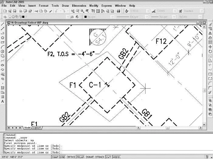
Figure 6-3:Lasso-ing objects with a WPolygon.
Ready, Get Set, Edit!
The following sections cover the most important AutoCAD editing commands, using command-first editing mode.
 Whether you start an AutoCAD editing command by clicking a toolbar button, choosing a pull-down menu command, or typing a command name, in almost all cases the command prompts you for points, distances, and options at the command line. Read the command line prompts during every step of the command, especially when you’re figuring out how to use a new editing command. Otherwise, you’re unlikely to complete the command successfully.
 As I describe in Chapter 4, maintaining precision when you draw and edit is crucial to good CAD work. If you’ve used a drawing program and are accustomed to moving, stretching, and otherwise editing objects by eye, you’ll need to suppress that habit when you edit in AutoCAD. Nothing ruins a drawing faster than approximate editing, in which you shove objects around until they look okay, without worrying about precise distances and points.
Moving, copying, and stretching are, for many drafters, the three most common editing operations. AutoCAD obliges this need with the Move, CoPy, and Stretch commands.
The Move, CoPy, and Stretch commands all require that you specify how far and in what direction you want the objects moved, copied, or stretched. After you’ve selected the objects to be edited and started the command, AutoCAD prompts you for two pieces of information:
Specify base point or displacement:
Specify second point of displacement or :
In a not-so-clear way, these prompts say that two possible methods exist for you to specify how far and in what direction you want the objects copied, moved, or stretched:
□ The most common way is to pick or type the coordinates of two points that define a displacement vector. AutoCAD calls these points the base point and the second point (hence, it’s called the “base point method”). Imagine an arrow pointing from the base point to the second point — that arrow defines how far and in what direction the objects get copied, moved, or stretched.
□ The other way is to type an X,Y pair of numbers that represents a distance rather than a point.This distance is the absolute displacement that you want to copy, move, or stretch the objects (thus it’s called the “displacement method”).
How does AutoCAD know whether your response to the first prompt is a base point or a displacement? It depends on how you respond to the second prompt. (Is that confusing, or what?) First, you pick a point on-screen or enter coordinates at the Base pointprompt. Next, there are a couple of possibilities:
□ If you then pick or type the coordinates of a point at the second point prompt, AutoCAD says to itself, “Aha — displacement vector!” and moves the objects according to the imaginary arrow pointing from the base point to the second point.
□ If you press Enter at the second prompt (without having typed anything), AutoCAD says, “Aha — displacement distance,” and uses the X,Y pair of numbers that you typed at the first prompt as an absolute displacement distance.
What makes this displacement business even more confusing is that AutoCAD lets you pick a point at the first prompt and press Enter at the second prompt. AutoCAD still says, “Aha — displacement distance,” but now it treats the coordinates of the point you picked as an absolute distance. If the point you picked has relatively large coordinates, the objects can get moved way outside the normal drawing area as defined by the limits. The objects fly off into space, which you probably won’t notice at first because you’re zoomed into part of your normal drawing area; it just looks to you like the objects have vanished!
In short, be careful when you press Enter during the Move, CoPy, and Stretch commands. Press Enter in response to the second prompt only if you want AutoCAD to use your response to the first prompt as an absolute displacement. If you make a mistake, click the Undo button to back up and try again. You can use Zoom Extents (described in Chapter 7) to look for objects that have flown off into space.
The following steps demonstrate command-first editing with the Move command, using the base point method of indicating how far and in what direction to move the selected objects. This procedure also gives detailed recommendations on how to use precision techniques when you edit:
Читать дальшеИнтервал:
Закладка:
Похожие книги на «AutoCAD 2005 for Dummies»
Представляем Вашему вниманию похожие книги на «AutoCAD 2005 for Dummies» списком для выбора. Мы отобрали схожую по названию и смыслу литературу в надежде предоставить читателям больше вариантов отыскать новые, интересные, ещё непрочитанные произведения.


Обсуждение, отзывы о книге «AutoCAD 2005 for Dummies» и просто собственные мнения читателей. Оставьте ваши комментарии, напишите, что Вы думаете о произведении, его смысле или главных героях. Укажите что конкретно понравилось, а что нет, и почему Вы так считаете.