Mark Middlebrook - AutoCAD 2005 for Dummies
Здесь есть возможность читать онлайн «Mark Middlebrook - AutoCAD 2005 for Dummies» — ознакомительный отрывок электронной книги совершенно бесплатно, а после прочтения отрывка купить полную версию. В некоторых случаях можно слушать аудио, скачать через торрент в формате fb2 и присутствует краткое содержание. Город: Indianapolis, Год выпуска: 2004, ISBN: 2004, Издательство: Wiley Publishing, Inc, Жанр: Программы, на английском языке. Описание произведения, (предисловие) а так же отзывы посетителей доступны на портале библиотеки ЛибКат.

- Название:AutoCAD 2005 for Dummies
- Автор:
- Издательство:Wiley Publishing, Inc
- Жанр:
- Год:2004
- Город:Indianapolis
- ISBN:0-7645-7138-9
- Рейтинг книги:5 / 5. Голосов: 1
-
Избранное:Добавить в избранное
- Отзывы:
-
Ваша оценка:
AutoCAD 2005 for Dummies: краткое содержание, описание и аннотация
Предлагаем к чтению аннотацию, описание, краткое содержание или предисловие (зависит от того, что написал сам автор книги «AutoCAD 2005 for Dummies»). Если вы не нашли необходимую информацию о книге — напишите в комментариях, мы постараемся отыскать её.
AutoCAD is more than just another application program, it’s a complete environment for drafting and design. So if you’re new to AutoCAD, you need to know several things to get off to a good start — especially how to use the command line area and set up your drawing properly. These key techniques are described in this part of the book.
If you’ve used earlier versions of AutoCAD, you’ll be most interested in the high points of the new release, including some newer interface components. The lowdown on what’s new is here, too.
AutoCAD 2005 for Dummies — читать онлайн ознакомительный отрывок
Ниже представлен текст книги, разбитый по страницам. Система сохранения места последней прочитанной страницы, позволяет с удобством читать онлайн бесплатно книгу «AutoCAD 2005 for Dummies», без необходимости каждый раз заново искать на чём Вы остановились. Поставьте закладку, и сможете в любой момент перейти на страницу, на которой закончили чтение.
Интервал:
Закладка:
Creating a donut is a simple way to define a single object that consists of two concentric circles with the space between them filled.
When you start the DOnut command, AutoCAD prompts you for the inside diameter and the outside diameter — the size of the hole and the size of the donut, as measured across their widest points. After you’ve entered these values, AutoCAD prompts you for the center point of the donut. But one donut is rarely enough, so AutoCAD keeps prompting you for additional center points until you press Enter (the AutoCAD equivalent of saying, “no, really, I’m full now!”).
The following example draws a regulation-size donut, with a 1.5-inch hole and 3.5-inch outside diameter. Figure 5-10 shows several kinds of donuts.
Command: DOnutEnter
Specify inside diameter of donut 0.5000: 1.5Enter
Specify outside diameter of donut 1.0000: 3.5Enter
Specify center of donut or exit:
pick or type the center point of one or more donuts
Specify center of donut or exit: Enter
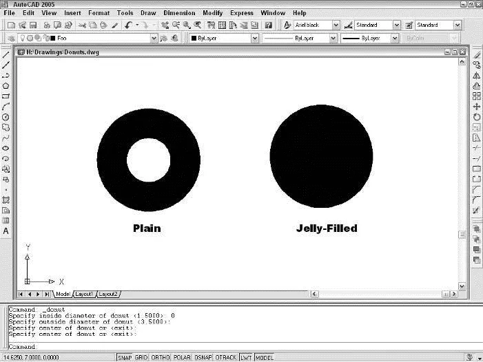
Figure 5-10:Donuts, plain and jelly-filled.
 You can use the DOnut command to create a filled circle — also known as a jelly-filled donut. Just specify an inside diameter of 0.
It’s customary in many industries to submit a set of drawings at a stage of completion and then submit them again later with revisions — corrections, clarifications, and requested changes. Often, the recipients like to locate changed stuff easily. A common drafting convention in many industries is to call attention to revised items by drawing free-form clouds around them. The REVCLOUD command makes quick work of drawing such clouds.
Drawing revision clouds is easy, after you understand that you click with the mouse only once in the drawing area. That one click defines the starting point for the cloud’s perimeter. After that, you simply move the cursor around, and the cloud takes shape. When you return to near the point that you clicked in the beginning, AutoCAD automatically closes the cloud.
The following example shows you how to draw a revision cloud. Figure 5-11 shows what revision clouds look like.
Command: REVCLOUD
Minimum arc length: 0.5000 Maximum arc length: 0.5000
Style: Normal
Specify start point or [Arc length/Object/Style] Object:
pick a point along the perimeter of your future cloud
Guide crosshairs along cloud path...
sweep the cursor around to define the cloud’s perimeter
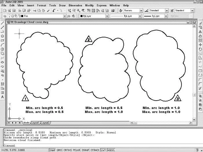
Figure 5-11:Cloud cover.
You don’t need to click again. Simply move the cursor around without clicking. AutoCAD draws the next lobe of the cloud when your cursor reaches the Minimum arc lengthdistance from the end of the previous lobe.
Continue moving the cursor around until you return to the point that you clicked at first.
Revision cloud finished.
Here are a few tips for using revision clouds:
□ It’s a good idea to put revision clouds on their own layer so that you can choose to plot with or without the clouds visible.
□ You’ll probably find it easier to control the shape of revision clouds if you turn off ortho mode before you start the command.
□ You may need to add a triangle and number, as shown in Figure 5-11, to indicate the revision number. A block with an attribute is a good way to handle this requirement: Chapter 13 covers blocks and attributes.
 If the revision cloud’s lobes are too small or too large, erase the cloud, restart the REVCLOUD command, and use the command’s
 Arc lengthoption to change the minimum and maximum arc lengths. The default minimum and maximum lengths are 0.5 (or 15 in metric drawings) multiplied by the DIMSCALE (DIMension SCALE) system variable setting. If you make the minimum and maximum lengths equal (which is the default), the lobes will be approximately equal in size. If you make them unequal, there will be more variation in lobe size — you’ll get “fluffier” clouds. Fortunately, of these options are more than most nonmeteorologists will need. If you’ve set DIMSCALE properly during your drawing setup procedure (see Chapter 3), REVCLOUD should do a pretty good job of guessing reasonable default arc lengths.
Scoring Points
I thought about not covering points in this book, but I didn’t want you complaining that AutoCAD 2005 For Dummies is pointless.
 The word point describes two different things in AutoCAD:
□ A location in the drawing that you specify (by typing coordinates or clicking with the mouse)
□ An object that you draw with the POint command
Throughout this chapter and most of the book, I tell you to specify points —
that’s the location meaning. This section tells you how to draw point objects.
A point object in AutoCAD can serve two purposes.
□ Points often identify specific locations in your drawing to other people who look at the drawing.A point can be something that displays on the screen, either as a tiny dot or as another symbol, such as a cross with a circle around it.
□ You can use points as precise object snap locations.Think of them as construction points. For example, when you’re laying out a new building, you might draw point objects at some of the engineering survey points and then snap to those points as you sketch the building’s shape with the polyline command. You use the NODe object snap mode to snap to AutoCAD point objects. In this guise, points usually are for your use in drawing and editing precisely. Other people who view the drawing probably won’t even be aware that the point objects are there.
What makes AutoCAD point objects complicated is their almost limitless range of display options, provided to accommodate the two different kinds of purposes just described (and possibly some others that I haven’t figured out yet). You use the Point Style dialog box, shown in Figure 5-12, to specify how points should look in the current drawing.
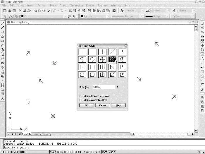
Figure 5-12:The Point Style dialog box controls the way point objects appear on-screen.
DDPTYPE is the command that opens the Point Style dialog box. You can access it from the menus by choosing Format→Point Style. The top portion of the dialog box shows the available point display styles. Most of the choices do pretty much the same thing. Just click one of the squares that says “hey, that’s a point!” to you.
Читать дальшеИнтервал:
Закладка:
Похожие книги на «AutoCAD 2005 for Dummies»
Представляем Вашему вниманию похожие книги на «AutoCAD 2005 for Dummies» списком для выбора. Мы отобрали схожую по названию и смыслу литературу в надежде предоставить читателям больше вариантов отыскать новые, интересные, ещё непрочитанные произведения.


Обсуждение, отзывы о книге «AutoCAD 2005 for Dummies» и просто собственные мнения читателей. Оставьте ваши комментарии, напишите, что Вы думаете о произведении, его смысле или главных героях. Укажите что конкретно понравилось, а что нет, и почему Вы так считаете.