Mark Middlebrook - AutoCAD 2005 for Dummies
Здесь есть возможность читать онлайн «Mark Middlebrook - AutoCAD 2005 for Dummies» — ознакомительный отрывок электронной книги совершенно бесплатно, а после прочтения отрывка купить полную версию. В некоторых случаях можно слушать аудио, скачать через торрент в формате fb2 и присутствует краткое содержание. Город: Indianapolis, Год выпуска: 2004, ISBN: 2004, Издательство: Wiley Publishing, Inc, Жанр: Программы, на английском языке. Описание произведения, (предисловие) а так же отзывы посетителей доступны на портале библиотеки ЛибКат.

- Название:AutoCAD 2005 for Dummies
- Автор:
- Издательство:Wiley Publishing, Inc
- Жанр:
- Год:2004
- Город:Indianapolis
- ISBN:0-7645-7138-9
- Рейтинг книги:5 / 5. Голосов: 1
-
Избранное:Добавить в избранное
- Отзывы:
-
Ваша оценка:
AutoCAD 2005 for Dummies: краткое содержание, описание и аннотация
Предлагаем к чтению аннотацию, описание, краткое содержание или предисловие (зависит от того, что написал сам автор книги «AutoCAD 2005 for Dummies»). Если вы не нашли необходимую информацию о книге — напишите в комментариях, мы постараемся отыскать её.
AutoCAD is more than just another application program, it’s a complete environment for drafting and design. So if you’re new to AutoCAD, you need to know several things to get off to a good start — especially how to use the command line area and set up your drawing properly. These key techniques are described in this part of the book.
If you’ve used earlier versions of AutoCAD, you’ll be most interested in the high points of the new release, including some newer interface components. The lowdown on what’s new is here, too.
AutoCAD 2005 for Dummies — читать онлайн ознакомительный отрывок
Ниже представлен текст книги, разбитый по страницам. Система сохранения места последней прочитанной страницы, позволяет с удобством читать онлайн бесплатно книгу «AutoCAD 2005 for Dummies», без необходимости каждый раз заново искать на чём Вы остановились. Поставьте закладку, и сможете в любой момент перейти на страницу, на которой закончили чтение.
Интервал:
Закладка:
□ Circle:Draws circles (you were expecting rectangles, maybe?)
□ Arc:Draws circular arcs — arcs cut from circles, not from ellipses, parabolas, or some other complicated curve
□ ELlipse:Draws ellipses and elliptical arcs
□ SPLine:Draws smoothly flowing curves of a variety of shapes
□ DOnut:Draws filled-in annular rings and circles
□ REVCLOUD:Draws free-form “clouds,” the most common application of which is to indicate revised areas in the drawing
The following sections describe each command.
AutoCAD offers an easy way to draw circles, and it also offers… other ways. The easy way is to define the center point of the circle and then to define the radius or diameter. You can also define a circle by entering one of the following options of the command (for those “other” ways):
□ 3P (3-Point):Specify any three points on the circumference.
□ 2P (2-Point):Specify the endpoints of a diameter of the circle.
□ Ttr (Tangent-Tangent-Radius):Specify two lines or other objects that are tangent to the circle, and then specify its radius.
Whether these additional circle-drawing methods are useful or superfluous depends on the kinds of drawings that you make and how geometry is defined in your industry. Get familiar with the default center point/radius method and then try the other methods to see whether they may be helpful to you. If you find yourself going around in circles, you can always draw them the default way and move them into position with other geometry.
1. Set object properties to the layer and other properties that you want applied to the circle that you’ll draw.
2. Click the Circle button on the Draw toolbar.
AutoCAD starts the Circle command and prompts you at the command line to specify the center point of the circle:
Specify center point for circle or [3P/2P/Ttr (tan tan radius)]:
The prompt shows the methods other than “center point plus radius” that you can use to draw circles in AutoCAD. (No, “tan tan radius” is not a mathematician’s dance.) Look up “CIRCLE command” in the online help if you think you may have a use for these less common circle-drawing methods.
3. Specify the center point by clicking a point or typing coordinates.
 Use one of the precision techniques described in Chapter 4 if you’re doing real drafting. Object snap, snap, and typing coordinates all work well for specifying the center point.
The command line then prompts you to specify the circle’s radius:
Specify radius of circle or [Diameter]:
Type Dand press Enter if you prefer to enter the diameter rather than the radius and you’ve forgotten your twos tables — or, more seriously, if the diameter is easier to specify with the cursor or type exactly than the radius is.
4. Specify the radius by typing a distance or clicking a point.
AutoCAD draws the circle, as shown in Figure 5-6.
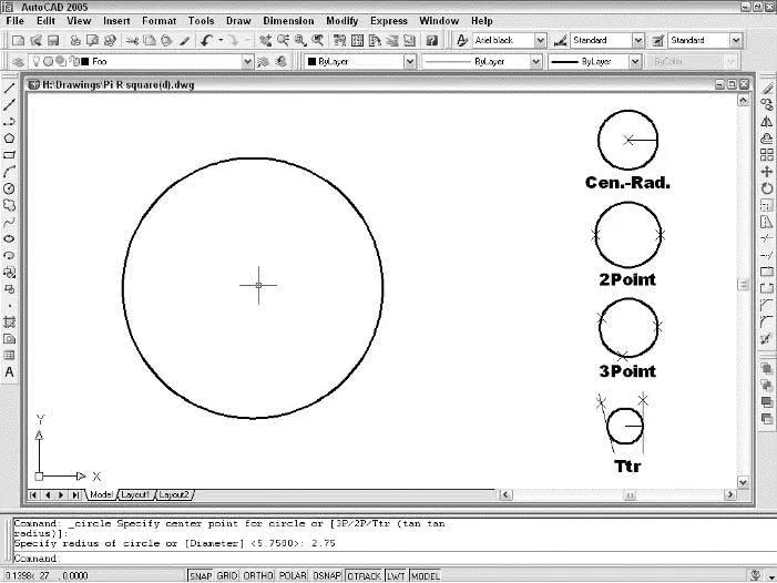
Figure 5-6:Pi R square(d); circles are round.
Arcs in AutoCAD are, quite simply, pieces of circles. As with circles, AutoCAD offers you an easy way to define arcs. Just specify three points on-screen to define the arc, easy as one-two-three. These points tell AutoCAD where to start the arc, how much to curve it, and where to end it.
Sounds pretty easy, right? So where’s the problem? The trouble is that you often must specify arcs more exactly than is possible by using this method. AutoCAD helps you specify such arcs, too, but the procedure ain’t easy.
You can start your arc by specifying the center of the arc or the start point. If you choose the Center option, AutoCAD prompts you for the center point first and the start point second. AutoCAD defines arcs counterclockwise, so pick a start point in a clockwise direction from the end point. After you specify the center and start point, AutoCAD presents several options you can choose, including the following:
□ Angle:This option specifies the included angle that the arc sweeps out. A 180-degree angle, for example, is a semicircle.
□ Length of chord:This option specifies the length of an imaginary straight line connecting the endpoints of the arc. Most people use this option seldom or never.
□ Endpoint:This option specifies where the arc ends. It’s the default option and is often the easiest to use.
If you specify the start point as the first option, you can choose among the following three command line options as well:
□ Center:This option prompts you for the arc’s center point and then finishes with the three options listed above.
□ End:This option specifies the endpoint of the arc. You then need to define the angle the arc covers, its direction, its radius, or its center point.
□ Second point:This is the default option. The second point you choose is not the endpoint; instead, it’s a point on the arc that, along with the start and endpoints, defines the arc’s curvature — that is, how much it curves. After you enter the second point, you must enter an endpoint to complete the arc. To get a feel for how these permutations can be strung together to create different arc-drawing methods, choose Draw→Arc and look at the impressive submenu that unfurls, as shown in Figure 5-7.
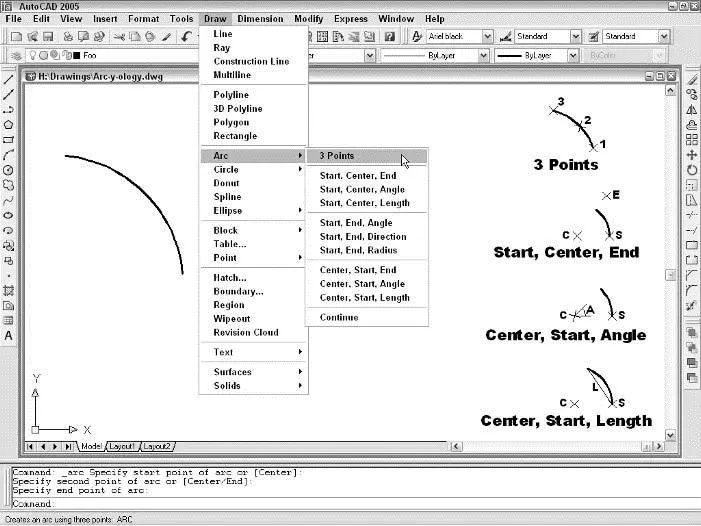
Figure 5-7:A deluge of Arc options, with the results of using some of those options.
The following example shows how you draw an arc with the default start point/second point/endpoint method:
1. Set object properties to the layer and other properties that you want applied to the arc that you’ll draw.
2. Click the Arc button on the Draw toolbar.
AutoCAD starts the Arc command and prompts you at the command line to specify the first endpoint of the arc:
Specify start point of arc or [Center]:
3. Specify the start point by clicking a point or typing coordinates.
The command line prompts you to specify a second point on the arc:
Specify second point of arc or [Center/ENd]:
4. Specify a second point on the arc by clicking a point or typing coordinates.
 The second point lies somewhere along the curve of the arc. AutoCAD determines the exact curvature of the arc after you choose the final endpoint in the following step. To align the second point with an existing object, use an object snap mode.
The command line prompts you to specify the other endpoint of the arc; as you move the cursor around, AutoCAD shows how the arc will look:
Читать дальшеИнтервал:
Закладка:
Похожие книги на «AutoCAD 2005 for Dummies»
Представляем Вашему вниманию похожие книги на «AutoCAD 2005 for Dummies» списком для выбора. Мы отобрали схожую по названию и смыслу литературу в надежде предоставить читателям больше вариантов отыскать новые, интересные, ещё непрочитанные произведения.


Обсуждение, отзывы о книге «AutoCAD 2005 for Dummies» и просто собственные мнения читателей. Оставьте ваши комментарии, напишите, что Вы думаете о произведении, его смысле или главных героях. Укажите что конкретно понравилось, а что нет, и почему Вы так считаете.