Mark Middlebrook - AutoCAD 2005 for Dummies
Здесь есть возможность читать онлайн «Mark Middlebrook - AutoCAD 2005 for Dummies» — ознакомительный отрывок электронной книги совершенно бесплатно, а после прочтения отрывка купить полную версию. В некоторых случаях можно слушать аудио, скачать через торрент в формате fb2 и присутствует краткое содержание. Город: Indianapolis, Год выпуска: 2004, ISBN: 2004, Издательство: Wiley Publishing, Inc, Жанр: Программы, на английском языке. Описание произведения, (предисловие) а так же отзывы посетителей доступны на портале библиотеки ЛибКат.

- Название:AutoCAD 2005 for Dummies
- Автор:
- Издательство:Wiley Publishing, Inc
- Жанр:
- Год:2004
- Город:Indianapolis
- ISBN:0-7645-7138-9
- Рейтинг книги:5 / 5. Голосов: 1
-
Избранное:Добавить в избранное
- Отзывы:
-
Ваша оценка:
AutoCAD 2005 for Dummies: краткое содержание, описание и аннотация
Предлагаем к чтению аннотацию, описание, краткое содержание или предисловие (зависит от того, что написал сам автор книги «AutoCAD 2005 for Dummies»). Если вы не нашли необходимую информацию о книге — напишите в комментариях, мы постараемся отыскать её.
AutoCAD is more than just another application program, it’s a complete environment for drafting and design. So if you’re new to AutoCAD, you need to know several things to get off to a good start — especially how to use the command line area and set up your drawing properly. These key techniques are described in this part of the book.
If you’ve used earlier versions of AutoCAD, you’ll be most interested in the high points of the new release, including some newer interface components. The lowdown on what’s new is here, too.
AutoCAD 2005 for Dummies — читать онлайн ознакомительный отрывок
Ниже представлен текст книги, разбитый по страницам. Система сохранения места последней прочитанной страницы, позволяет с удобством читать онлайн бесплатно книгу «AutoCAD 2005 for Dummies», без необходимости каждый раз заново искать на чём Вы остановились. Поставьте закладку, и сможете в любой момент перейти на страницу, на которой закончили чтение.
Интервал:
Закладка:
□ The Line command draws a series of single line segment objects. Even though they appear on the screen to be linked, each segment is a separate object. If you move one line segment, the other segments that you drew at the same time don’t move with it. The PLine command, on the other hand, draws a single, connected, multisegment object. If you select any segment for editing, your changes affect the entire polyline. Figure 5-2 shows how the same sketch drawn with the Line and the PLine commands responds when you select one of the objects.
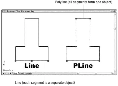
Figure 5-2:Results of drawing with the Line and PLine commands.
 Use the PLine command instead of Line in most cases where you need to draw a series of connected line segments. If you’re drawing a series of endto-end segments, there’s a good chance that those segments are logically connected — for example, they might represent the outline of a single object or a continuous pathway. If the segments are connected logically, it makes sense to keep them connected in AutoCAD. The most obvious practical benefit of grouping segments together into a polyline is that many editing operations are more efficient when you use polylines. If you move a single, disconnected line segment, the other segments that you drew at the same time don’t move with it — likewise for other common editing operations, such as copying, erasing, rotating, and mirroring. When you select any segment in a polyline for editing, the entire polyline is affected.
□ The PLine command can draw curved segments as well as straight ones.
□ You can add width to each segment of a polyline. Polyline segment width is similar to lineweight, except that it can be uniform or tapered. The ability to create polyline segments with line widths was more important in the old days before AutoCAD had lineweight as an object property. People used to draw polylines with a small amount of width to show the segments as somewhat heavier than normal on plots. Nowadays, it’s easier and more efficient to achieve this effect with object lineweights (as described in Chapter 4) or plot styles (as described in Chapter 12).
After you create a polyline, you can adjust its segments by grip editing any of the vertex points. (The little squares on the vertices in Figure 5-2 are called grips; see Chapter 6 for details on grip editing.) For more complicated polyline editing tasks, you can use the PEdit command to edit the polyline, or you can convert the polyline to a collection of line and arc segments by using the eXplode command — although you lose any width defined for each segment when you explode a polyline.
Drawing polylines composed of straight segments is pretty much like drawing with the Line command, as demonstrated in the following procedure. Watch the command prompts carefully because the PLine command has a lot of options! Remember that you can right-click in the drawing area to select one of the options, but reading the command prompts is your ticket to knowing what the options are at any moment.
To draw a polyline composed of straight segments, follow these steps:
1. Set object properties to the layer and other properties that you want applied to the polyline object that you’ll draw.
2. Click the Polyline button — the one that looks like a fishhook — on the Draw toolbar.
AutoCAD starts the PLine command and prompts you at the command line:
Specify start point:
3. Specify the starting point by clicking a point or typing coordinates.
AutoCAD displays the current polyline segment line-width and prompts you to specify the other endpoint of the first polyline segment:
Current line-width is 0.0000
Specify next point or [Arc/Halfwidth/Length/Undo/Width]:
4. If the current line-width isn’t zero, change it to zero by typingW , Enter,0 , Enter,0 (as shown in the following command line sequence).
Specify next point or [Arc/Halfwidth/Length/Undo/Width]: W
Enter Specify starting width 0.0000: 0
Enter Specify ending width 0.0000: 0
Enter Specify next point or [Arc/Halfwidth/Length/Undo/Width]:
Despite what you may think, a zero width polyline segment is not the AutoCAD equivalent of writing with disappearing ink. “Zero width” means “display this segment, using the normal, thin line-width on the screen.” AutoCAD still applies object property or plot style lineweights when you plot.
5. Specify additional points by clicking or typing.
After you specify the second point, AutoCAD adds the Close option to the command line prompt:
Specify next point or [Arc/Close/Halfwidth/Length/Undo/Width]:
In addition, you can view and choose options from the right-click menu, as shown in Figure 5-3.
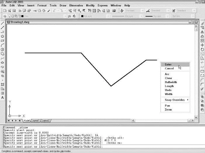
Figure 5-3:Getting in the PLine.
6. After you finish drawing segments, either press Enter (to leave the figure open) or typeC and press Enter (to close it).
AutoCAD draws the final segment and returns to the Commandprompt, indicating that the PLine command is finished:
Command:
In the following procedure, I spice things up a bit and give you a preview of coming (curvy) attractions by adding an arc segment to a polyline.
 Just so you know, curved segments in polylines are circular arcs — pieces of circles that you can draw with the AutoCAD Arc command. AutoCAD can draw other kinds of curves, including ellipses and splines, but not within the PLine command.
To draw a polyline that includes curved segments, follow these steps:
1. Repeat Steps 1 through 5 of the previous procedure.
2. When you’re ready to add one or more arc segments, typeA and press Enter to select the Arc option.
The command line prompt changes to show arc segment options. Most of these options correspond to the many ways of drawing circular arcs in AutoCAD; see “Arc-y-ology,” later in this chapter.
Specify endpoint of arc or
[Angle/CEnter/CLose/Direction/Halfwidth/Line/Radius/Second pt/Undo/Width]:
3. Specify the endpoint of the arc by clicking a point or typing coordinates.
AutoCAD draws the curved segment of the polyline. The command line prompt continues to show arc segment options.
Specify endpoint of arc or
[Angle/CEnter/CLose/Direction/Halfwidth/Line/Radius/Second pt/Undo/Width]:
Your options at this point include
• Specifying additional points to draw more arc segments
• Choosing another arc-drawing method (such as CEnteror Second pt)
• Returning to drawing straight-line segments with the Line option
In this example, I return to drawing straight-line segments.
Perhaps the most useful of the alternative arc-drawing methods is Second pt. You can use it to gain flexibility in the direction of the arc, but at the cost of losing tangency of contiguous segments. Sometimes it’s best not to go off on a tangent, anyway.
Интервал:
Закладка:
Похожие книги на «AutoCAD 2005 for Dummies»
Представляем Вашему вниманию похожие книги на «AutoCAD 2005 for Dummies» списком для выбора. Мы отобрали схожую по названию и смыслу литературу в надежде предоставить читателям больше вариантов отыскать новые, интересные, ещё непрочитанные произведения.


Обсуждение, отзывы о книге «AutoCAD 2005 for Dummies» и просто собственные мнения читателей. Оставьте ваши комментарии, напишите, что Вы думаете о произведении, его смысле или главных героях. Укажите что конкретно понравилось, а что нет, и почему Вы так считаете.