Mark Middlebrook - AutoCAD 2005 for Dummies
Здесь есть возможность читать онлайн «Mark Middlebrook - AutoCAD 2005 for Dummies» — ознакомительный отрывок электронной книги совершенно бесплатно, а после прочтения отрывка купить полную версию. В некоторых случаях можно слушать аудио, скачать через торрент в формате fb2 и присутствует краткое содержание. Город: Indianapolis, Год выпуска: 2004, ISBN: 2004, Издательство: Wiley Publishing, Inc, Жанр: Программы, на английском языке. Описание произведения, (предисловие) а так же отзывы посетителей доступны на портале библиотеки ЛибКат.

- Название:AutoCAD 2005 for Dummies
- Автор:
- Издательство:Wiley Publishing, Inc
- Жанр:
- Год:2004
- Город:Indianapolis
- ISBN:0-7645-7138-9
- Рейтинг книги:5 / 5. Голосов: 1
-
Избранное:Добавить в избранное
- Отзывы:
-
Ваша оценка:
AutoCAD 2005 for Dummies: краткое содержание, описание и аннотация
Предлагаем к чтению аннотацию, описание, краткое содержание или предисловие (зависит от того, что написал сам автор книги «AutoCAD 2005 for Dummies»). Если вы не нашли необходимую информацию о книге — напишите в комментариях, мы постараемся отыскать её.
AutoCAD is more than just another application program, it’s a complete environment for drafting and design. So if you’re new to AutoCAD, you need to know several things to get off to a good start — especially how to use the command line area and set up your drawing properly. These key techniques are described in this part of the book.
If you’ve used earlier versions of AutoCAD, you’ll be most interested in the high points of the new release, including some newer interface components. The lowdown on what’s new is here, too.
AutoCAD 2005 for Dummies — читать онлайн ознакомительный отрывок
Ниже представлен текст книги, разбитый по страницам. Система сохранения места последней прочитанной страницы, позволяет с удобством читать онлайн бесплатно книгу «AutoCAD 2005 for Dummies», без необходимости каждый раз заново искать на чём Вы остановились. Поставьте закладку, и сможете в любой момент перейти на страницу, на которой закончили чтение.
Интервал:
Закладка:
4. TypeL and press Enter to select the Line option.
Specify endpoint of arc or
[Angle/CEnter/CLose/Direction/Halfwidth/Line/Radius/Second pt/Undo/Width]: L
The command line prompt changes back to showing straight-line segment options.
Specify next point or
[Arc/Close/Halfwidth/Length/Undo/Width]:
5. Specify additional points by clicking or typing.
6. After you’re finished drawing segments, either press Enter or typeC and press Enter.
Command:
Figure 5-4 shows some of the things that you can draw with the PLine command by using straight segments, arc segments, or a combination of both.
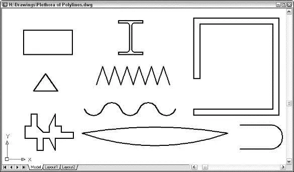
Figure 5-4:A plethora of polylines.
 The Line and PLine commands work well for drawing a series of end-to-end single lines, but what if you want to draw a series of double lines to represent, for example, the edges of a wall or roadway? Here are three options:
□ Use the AutoCAD MLine command to draw multilines — series of two or more parallel, straight lines. The AutoCAD multiline feature was full of limitations and bugs when it debuted ten years ago. It hasn’t improved significantly since then. Look up the MLine and MLSTYLE commands in AutoCAD’s online help system if you’d like to tangle with this feature, but be prepared to spend time experimenting and struggling.
 □ In AutoCAD LT only, use the DLine (Double Line) command to draw pairs of parallel line and/or arc segments. AutoCAD LT doesn’t include the MLine command, which, given MLine’s problems, probably is more of a blessing than a limitation. AutoCAD, on the other hand, doesn’t include the DLine command. (Score one for the little brother!)
□ Use the PLine command to draw a single set of connected line and/or arc segments, and then use the Offset command to create one or more sets of parallel segments. Chapter 6 covers the Offset command.
You can use the PLine or Line command to draw a rectangle segment by segment. In most cases, though, you’ll find it easier to use the special-purpose RECtang command. The following procedure demonstrates how:
1. Set object properties to the layer and other properties that you want applied to the rectangle that you’ll draw.
2. Click the Rectangle button on the Draw toolbar.
AutoCAD starts the RECtang command and prompts you at the command line to specify a point for one corner of the rectangle:
Specify first corner point or
[Chamfer/Elevation/Fillet/Thickness/Width]:
You can add fancy effects with the additional command options. The default options work best for most purposes. Look up “RECTANG command” in the AutoCAD help system if you want to know more about the options.
3. Specify the first corner by clicking a point or typing coordinates.
The command line prompts you to specify the other corner of the rectangle — the one that’s diagonally opposite from the first corner:
Specify other corner point or [Dimensions]:
4. Specify the other corner by clicking a point or typing coordinates.
If you know the size of the rectangle that you want to draw (for example, 100 units long by 75 units high), type relative coordinates to specify the dimensions (for example, @100,75). (Chapter 4 describes how to type coordinates.)
AutoCAD draws the rectangle.
Rectangles and other closed polylines are types of polygons , or closed figures with three or more sides. The AutoCAD POLygon command provides a quick way of drawing regular polygons — polygons in which all sides and angles are equal. (If regular polygons seem a little square, maybe that’s because a square is a special case of a regular polygon!)
The following procedure demonstrates the POLygon command:
1. Set object properties to the layer and other properties that you want applied to the polygon that you’ll draw.
2. Click the Polygon button on the Draw toolbar.
AutoCAD starts the POLygon command and prompts you at the command line to enter the number of sides for the polygon:
Enter number of sides <4>:
3. Type the number of sides in the polygon that you want to draw and press Enter.
The command line prompts you to specify the center point of the polygon:
Specify center of polygon or [Edge]:
You can use the Edge option to draw a polygon by specifying one side, instead of the center and radius of an imaginary inscribed or circumscribed circle. The imaginary circle method is much more common.
4. Specify the center point by clicking a point or typing coordinates.
The command line prompts you to specify whether the polygon will be inscribed in or circumscribed about an imaginary circle whose radius you will specify in the following step:
Enter an option [Inscribed in circle/Circumscribed about circle] :
5. TypeI orC and press Enter.
The command line prompts you to specify the radius of imaginary circle:
Specify radius of circle:
6. Specify the radius by typing a distance or clicking a point.
AutoCAD draws the polygon.
If you type a distance or you click a point with Ortho turned on, the polygon will be aligned orthogonally, as shown in Figure 5-5. If you click a point with Ortho turned off, the polygon most likely won’t be aligned orthogonally.
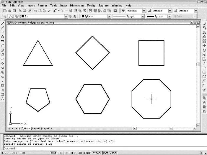
Figure 5-5:A polygonal party.
Figure 5-5 shows the results of drawing plenty of polygons — a practice known as “polygony,” and which, as far as I know, remains legal in most states.
 Rectangles and polygons in AutoCAD are really just polylines that you specify in a way that’s appropriate to the shape you’re creating. You’ll notice this when you grip edit a rectangle or polygon and move one of the vertexes: Only the selected vertex moves. AutoCAD doesn’t make the entire rectangle or polygon larger or smaller. (See Chapter 6 for information about grip editing.)
(Throwing) Curves
Although straight line segments predominate in many CAD drawings, even the most humdrum, rectilinear design is likely to have a few curves. And if you’re drawing car bodies or Gaudí buildings, your drawings will be almost nothing but curves! This section shows you how to use the following AutoCAD curve-drawing commands:
Читать дальшеИнтервал:
Закладка:
Похожие книги на «AutoCAD 2005 for Dummies»
Представляем Вашему вниманию похожие книги на «AutoCAD 2005 for Dummies» списком для выбора. Мы отобрали схожую по названию и смыслу литературу в надежде предоставить читателям больше вариантов отыскать новые, интересные, ещё непрочитанные произведения.


Обсуждение, отзывы о книге «AutoCAD 2005 for Dummies» и просто собственные мнения читателей. Оставьте ваши комментарии, напишите, что Вы думаете о произведении, его смысле или главных героях. Укажите что конкретно понравилось, а что нет, и почему Вы так считаете.