Stephen Rolt - Optical Engineering Science
Здесь есть возможность читать онлайн «Stephen Rolt - Optical Engineering Science» — ознакомительный отрывок электронной книги совершенно бесплатно, а после прочтения отрывка купить полную версию. В некоторых случаях можно слушать аудио, скачать через торрент в формате fb2 и присутствует краткое содержание. Жанр: unrecognised, на английском языке. Описание произведения, (предисловие) а так же отзывы посетителей доступны на портале библиотеки ЛибКат.
- Название:Optical Engineering Science
- Автор:
- Жанр:
- Год:неизвестен
- ISBN:нет данных
- Рейтинг книги:3 / 5. Голосов: 1
-
Избранное:Добавить в избранное
- Отзывы:
-
Ваша оценка:
Optical Engineering Science: краткое содержание, описание и аннотация
Предлагаем к чтению аннотацию, описание, краткое содержание или предисловие (зависит от того, что написал сам автор книги «Optical Engineering Science»). Если вы не нашли необходимую информацию о книге — напишите в комментариях, мы постараемся отыскать её.
Offers a comprehensive review of the topic of optical engineering Covers topics such as optical fibers, waveguides, aspheric surfaces, Zernike polynomials, polarisation, birefringence and more Targets engineering professionals and students Filled with illustrative examples and mathematical equations Written for professional practitioners, optical engineers, optical designers, optical systems engineers and students,
offers an authoritative guide that covers the broad range of optical design and optical metrology topics and their applications.
Optical Engineering Science — читать онлайн ознакомительный отрывок
Ниже представлен текст книги, разбитый по страницам. Система сохранения места последней прочитанной страницы, позволяет с удобством читать онлайн бесплатно книгу «Optical Engineering Science», без необходимости каждый раз заново искать на чём Вы остановились. Поставьте закладку, и сможете в любой момент перейти на страницу, на которой закончили чтение.
Интервал:
Закладка:
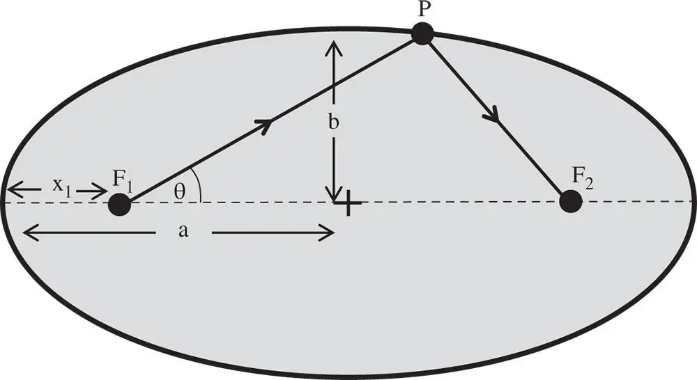
Figure 5.1 Ellipsoid of revolution.
(5.2) 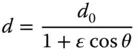
The parameter, ε, is the so-called eccentricity of the ellipse and is related to the conic parameter, k. In addition, the parameter, d 0is related to the base radius, R , as defined in the conic section formula in Eq. (5.1). The connection between the parameters is as set out in Eq. (5.3):
(5.3) 
From the perspective of image formation, the two focal points, F 1and F 2represent the ideal object and image locations for this conic section. If x 1in Figure 5.1represents the object distance u , i.e. the distance from the object to the nearest surface vertex, then it is also possible to calculate the distance, v , to the other focal point. These distances are presented below in the form of Eq. (5.2):
(5.4) 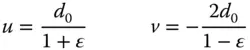
From the above, it is easy to calculate the conjugate parameter for this conjugate pair:
In fact, object and image conjugates are reversible, so the full solution for the conic constant is as in Eq. (5.5):
(5.5) 
Thus, it is straightforward to demonstrate that for a conic section, there exists one pair of conjugates for which perfect image formation is possible. Of course, the most well known of these is where k = −1, which defines the paraboloidal shape. From Eq. (5.5), the corresponding conjugate parameter is −1 and relates to the infinite conjugate. This forms the basis of the paraboloidal mirror used widely (at the infinite conjugate) in reflecting telescopes and other imaging systems.
As for the spherical mirror, the effective focal length of the mirror remains the same as for the paraxial relationship:
(5.6) 
More generally, the spherical aberration produced by a conic mirror is of a similar form as for the spherical mirror but with an offset:
(5.7) 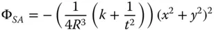
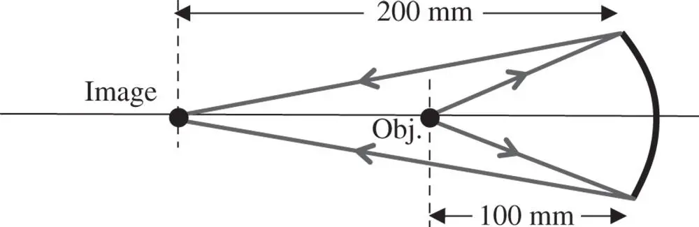
Worked Example 5.1 Simple Mirror-Based Magnifier
We wish to construct a simple magnification system with a simple conic mirror. The system magnification is to be two and the object distance 100 mm. There is to be no on axis aberration. What is the prescription of the mirror, i.e. base radius and conic constant?
It is assumed that object and image are located the same side of the mirror, so that, in this context, the image distance is −200 mm. The overall set up is illustrated in the diagram:
The base radius of the conic mirror is very simple to calculate as it follows the simple paraxial formula, as replicated in Eq. (5.6):
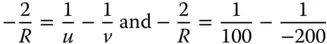
This gives R = −133 mm.
We now need to calculate the conjugate parameter, t :
From Eq. (5.5)it is straightforward to see that k = −(1/ t ) 2and thus k = −0.1111. The shape is that of a slightly prolate ellipsoid.
The practical significance of a perfect on axis set up described in this example, is that it forms the basis of an ideal manufacturing test for such a conic surface. This will be described in more detail later in this text.
5.2.3 Conic Refracting Surfaces
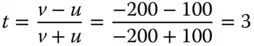
There is no generic rule for conic refracting surfaces that generate perfect image formation for an arbitrary conjugate. However, there is a special condition for the infinite conjugate where perfect image formation results, as illustrated in Figure 5.2.
If the refractive index of the surface is n , assuming that the object is in air/vacuum, then the conic constant of the ideal surface is – n 2. In fact, the shape is that of a hyperboloid. The abscissa of the hyperboloid effectively produce grazing incidence for rays originating from the object. By definition, therefore, the angle that the surface normal makes with the optical axis at the abscissa is equal to the critical angle. This restricts the maximum numerical aperture that can be collected by the system. With this constraint, it is clear that the maximum numerical aperture is equal to 1/ n . In summary therefore:
(5.8) 
Unfortunately, no other general condition for perfect image formation results for a conic surface. However, for perfect image correction, all orders of (on axis) aberration are corrected. Thus, although no condition for perfect image formation is possible, it is still possible, nevertheless, to correct for third order spherical aberration with a single refractive surface.
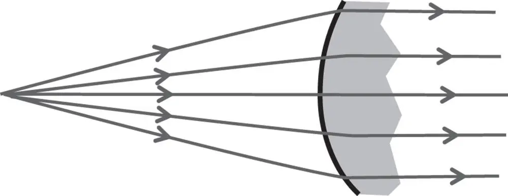
Figure 5.2 Single refractive surface at infinite conjugate.
5.2.4 Optical Design Using Aspheric Surfaces
The preceding discussion largely focused on perfect imaging in specific and restricted circumstances. However, even where perfect imaging is not theoretically possible, aspheric surfaces are extremely useful in the correction of system aberrations with a minimum number of surfaces. For more general design problems, therefore, even asphere terms may be added to the surface prescription. With the stop located at a specific surface, adding aspheric terms to the form of that surface can only control the spherical aberration at that surface. One perspective on the form of a surface is that second order terms only add to the power of that surface, whereas fourth order terms control the third order (in transverse aberration) aberrations. The reasoning behind this assertion may be viewed a little more clearly by expanding the sag of a conic surface in terms of even polynomial terms:
(5.9) 
Интервал:
Закладка:
Похожие книги на «Optical Engineering Science»
Представляем Вашему вниманию похожие книги на «Optical Engineering Science» списком для выбора. Мы отобрали схожую по названию и смыслу литературу в надежде предоставить читателям больше вариантов отыскать новые, интересные, ещё непрочитанные произведения.


Обсуждение, отзывы о книге «Optical Engineering Science» и просто собственные мнения читателей. Оставьте ваши комментарии, напишите, что Вы думаете о произведении, его смысле или главных героях. Укажите что конкретно понравилось, а что нет, и почему Вы так считаете.