Stephen Rolt - Optical Engineering Science
Здесь есть возможность читать онлайн «Stephen Rolt - Optical Engineering Science» — ознакомительный отрывок электронной книги совершенно бесплатно, а после прочтения отрывка купить полную версию. В некоторых случаях можно слушать аудио, скачать через торрент в формате fb2 и присутствует краткое содержание. Жанр: unrecognised, на английском языке. Описание произведения, (предисловие) а так же отзывы посетителей доступны на портале библиотеки ЛибКат.
- Название:Optical Engineering Science
- Автор:
- Жанр:
- Год:неизвестен
- ISBN:нет данных
- Рейтинг книги:3 / 5. Голосов: 1
-
Избранное:Добавить в избранное
- Отзывы:
-
Ваша оценка:
Optical Engineering Science: краткое содержание, описание и аннотация
Предлагаем к чтению аннотацию, описание, краткое содержание или предисловие (зависит от того, что написал сам автор книги «Optical Engineering Science»). Если вы не нашли необходимую информацию о книге — напишите в комментариях, мы постараемся отыскать её.
Offers a comprehensive review of the topic of optical engineering Covers topics such as optical fibers, waveguides, aspheric surfaces, Zernike polynomials, polarisation, birefringence and more Targets engineering professionals and students Filled with illustrative examples and mathematical equations Written for professional practitioners, optical engineers, optical designers, optical systems engineers and students,
offers an authoritative guide that covers the broad range of optical design and optical metrology topics and their applications.
Optical Engineering Science — читать онлайн ознакомительный отрывок
Ниже представлен текст книги, разбитый по страницам. Система сохранения места последней прочитанной страницы, позволяет с удобством читать онлайн бесплатно книгу «Optical Engineering Science», без необходимости каждый раз заново искать на чём Вы остановились. Поставьте закладку, и сможете в любой момент перейти на страницу, на которой закончили чтение.
Интервал:
Закладка:
1.4.4 Refraction at Two Spherical Surfaces (Lenses)
Figure 1.14shows a lens made up of two spherical surfaces, of radius, R 1and R 2. Once again, the convention is that the spherical radius is positive if the centre of curvature lies to the right of the relevant vertex.
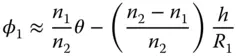
So, in the biconvex lens illustrated in Figure 1.14, the first surface has a positive radius of curvature and the second surface has a negative radius of curvature. The lens is made from a material of refractive index n 2and is bounded by two surfaces with radius of curvature R 1and R 2respectively. It is immersed totally in a medium of refractive index, n 1(e.g. air). In addition, it is assumed that the lens has negligible thickness ( the thin lens approximation). Of course, as for the treatment of the single curved surface, we assume all angles are small and θ ∼ sinθ. First, we might calculate the angle of refraction, φ 1, produced by the first curved surface, R 1. This can be calculated using Eq. (1.14):
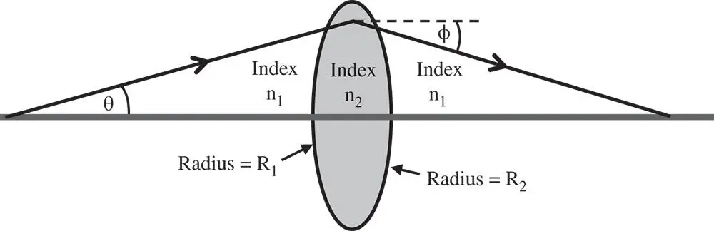
Figure 1.14 Refraction by two spherical surfaces (lens).
Of course, the final angle, φ, can be calculated from φ 1by another application of Eq. (1.14):
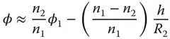
Substituting for φ 1we get:
(1.15) 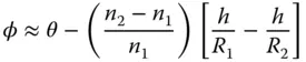
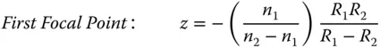
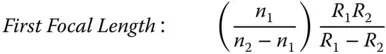
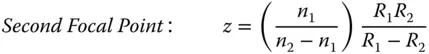
As for Eq. (1.14)there are two parts to Eq. (1.15). First, there is an angular term that is equal to the incident angle. Second, there is a focusing contribution that produces a deflection proportional to ray height. Equation (1.15)allows the tracing of all rays in a system containing the single lens and it is straightforward to calculate the Cardinal points of the thin lens: Cardinal points for a thin lens
 |
 |
 |
 |
| Both Principal Points: At centre of lens | |
| Both Nodal Points: At centre of lens |
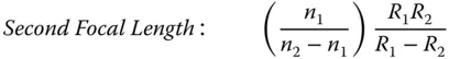
Since both object and image spaces are in the same media, then both focal lengths are equal and the principal and nodal points are co-located. One can take the above expressions for focal length and cast it in a more conventional form as a singlefocal length, f . This gives the so-called Lensmaker's Equation, where it is assumed that the surrounding medium (air) has a refractive index of one (i.e. n 1= 1) and we substitute n for n 2.
(1.16) 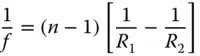
1.4.5 Reflection by a Plane Surface
Figure 1.15shows the process of reflection at a plane surface. As in the previous case of refraction, the reflected ray lies in the same plane as the incident ray and the angle of reflection is equal and opposite to the angle of incidence.
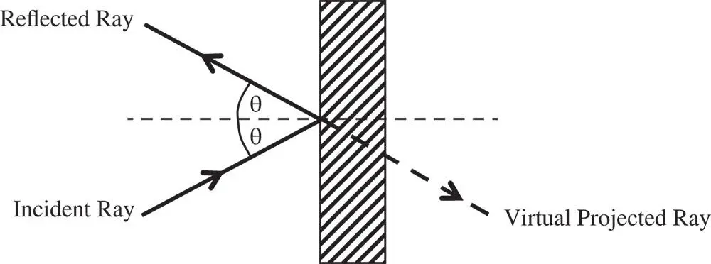
Figure 1.15 Reflection at a plane surface.
The virtual projected ray shown in Figure 1.15illustrates an important point about reflection. If one considers the process as analogous to refraction, then a mirror behaves as a refractive material with an index of −1. This, in itself has an important consequence. The image produced is inverted in space. As such, there is no combination of positive magnification and pure rotation that will map the image onto the object. That is to say, a right handed object will be converted into a left handed image. More generally, if an optical system contains an odd number of reflective elements, the parity of the image will be reversed. So, for example, if a complex optical system were to contain nine reflective elements in the optical path, then the resultant image could not be generated from the object by rotation alone. Conversely, if the optical system were to contain an even number of reflective surfaces, then the parity between the object and image geometries would be conserved.
Another way in which a plane mirror is different from a plane refractive surface is that a plane mirror is the one (and perhaps only) example of a perfect imaging system. Regardless of any approximation with regard to small angles discussed previously, following reflection at a planar surface, all raysdiverging from a single image point would, when projected as in Figure 1.15, be seen to emerge exactlyfrom a singleobject point.
1.4.6 Reflection from a Curved (Spherical) Surface
Figure 1.16illustrates the reflection of a ray from a curved surface.
The incident ray is at an angle, θ, with respect to the optical axis and the reflected ray is at an angle, ϕ to the optical axis. If we designate the incident angle as θ 1and the reflected angle as θ 2(with respect to the local surface normal), then the following apply, assuming all relevant angles are small:
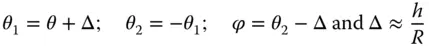
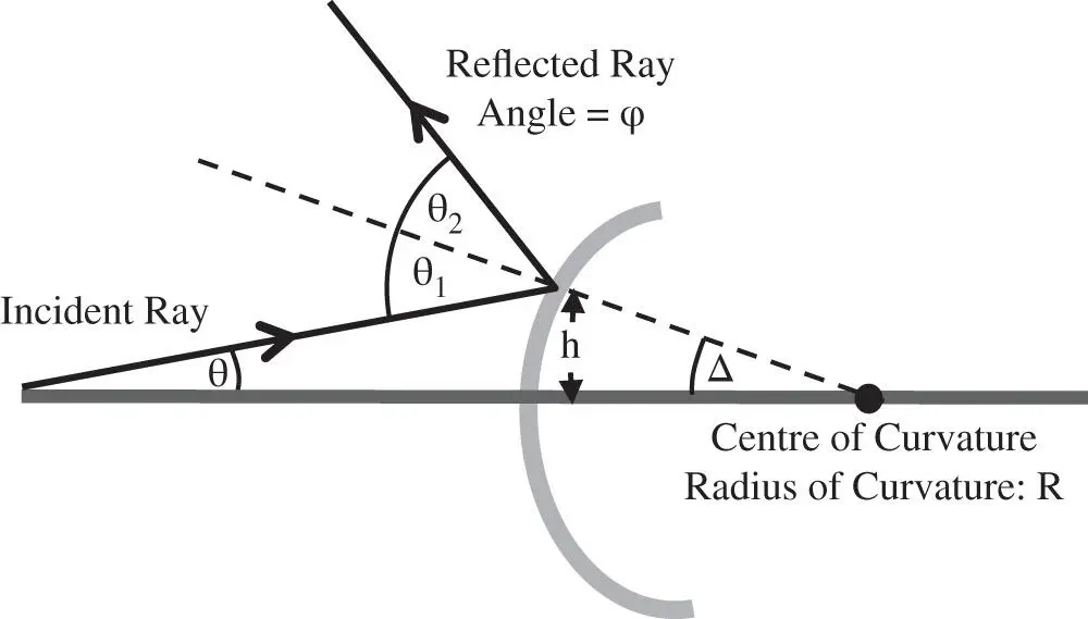
Figure 1.16 Reflection from a curved surface.
We now need to calculate the angle, ϕ, the refracted ray makes to the optical axis:
(1.17) 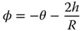
In form, Eq. (1.17)is similar to Eq. (1.14)with a linear dependence of the reflected ray angle on both incident ray angle and height. The two equations may be made to correspond exactly if we make the substitution, n 1= 1, n 2= −1. This runs in accord with the empirical observation made previously that a reflective surface acts like a medium with a refractive index of −1. Once more, the sign convention observed dictates that positive axial displacement, z , is in the direction from left to right and positive height is vertically upwards. A ray with a positive angle, θ, has a positive gradient in h with respect to z .
Читать дальшеИнтервал:
Закладка:
Похожие книги на «Optical Engineering Science»
Представляем Вашему вниманию похожие книги на «Optical Engineering Science» списком для выбора. Мы отобрали схожую по названию и смыслу литературу в надежде предоставить читателям больше вариантов отыскать новые, интересные, ещё непрочитанные произведения.


Обсуждение, отзывы о книге «Optical Engineering Science» и просто собственные мнения читателей. Оставьте ваши комментарии, напишите, что Вы думаете о произведении, его смысле или главных героях. Укажите что конкретно понравилось, а что нет, и почему Вы так считаете.