Zhuming Bi - Computer Aided Design and Manufacturing
Здесь есть возможность читать онлайн «Zhuming Bi - Computer Aided Design and Manufacturing» — ознакомительный отрывок электронной книги совершенно бесплатно, а после прочтения отрывка купить полную версию. В некоторых случаях можно слушать аудио, скачать через торрент в формате fb2 и присутствует краткое содержание. Жанр: unrecognised, на английском языке. Описание произведения, (предисловие) а так же отзывы посетителей доступны на портале библиотеки ЛибКат.
- Название:Computer Aided Design and Manufacturing
- Автор:
- Жанр:
- Год:неизвестен
- ISBN:нет данных
- Рейтинг книги:3 / 5. Голосов: 1
-
Избранное:Добавить в избранное
- Отзывы:
-
Ваша оценка:
Computer Aided Design and Manufacturing: краткое содержание, описание и аннотация
Предлагаем к чтению аннотацию, описание, краткое содержание или предисловие (зависит от того, что написал сам автор книги «Computer Aided Design and Manufacturing»). Если вы не нашли необходимую информацию о книге — напишите в комментариях, мы постараемся отыскать её.
Computer Aided Design and Manufacturing being uniquely structured to classify and align engineering disciplines and computer aided technologies from the perspective of the design needs in whole product life cycles, utilizing a comprehensive Solidworks package (add-ins, toolbox, and library) to showcase the most critical functionalities of modern computer aided tools, and presenting real-world design projects and case studies so that readers can gain CAD and CAM problem-solving skills upon the CAD/CAM theory.
is an ideal textbook for undergraduate and graduate students in mechanical engineering, manufacturing engineering, and industrial engineering. It can also be used as a technical reference for researchers and engineers in mechanical and manufacturing engineering or computer-aided technologies.
Computer Aided Design and Manufacturing — читать онлайн ознакомительный отрывок
Ниже представлен текст книги, разбитый по страницам. Система сохранения места последней прочитанной страницы, позволяет с удобством читать онлайн бесплатно книгу «Computer Aided Design and Manufacturing», без необходимости каждый раз заново искать на чём Вы остановились. Поставьте закладку, и сможете в любой момент перейти на страницу, на которой закончили чтение.
Интервал:
Закладка:
2.6 Interactive Feature‐Based Modelling Using CAD Tools
A SolidWorks modelling environment is used to illustrate the application of interactive feature‐based modelling. As shown in Figure 2.38, a part usually consists of a number of features. The corresponding solid of a feature can be added or removed from the volume of the part model by an Operator , which is associated with the feature type. The geometry and shape of a feature can be created by built‐in tools (e.g. Fillet or Chamber ) or sketch tools (e.g. Extruded Boss or Cut ). The parameters for dimensions and relations are defined when a feature is created. Each built‐in tool is equipped with a wizard to guide user inputs. The sketch tools provide the flexibility for the user to define the dimensions of a feature by hand. Finally, all sketches, paths, dimensions, and constraints are defined upon certain references such as points, axes, planes, and coordinate systems.
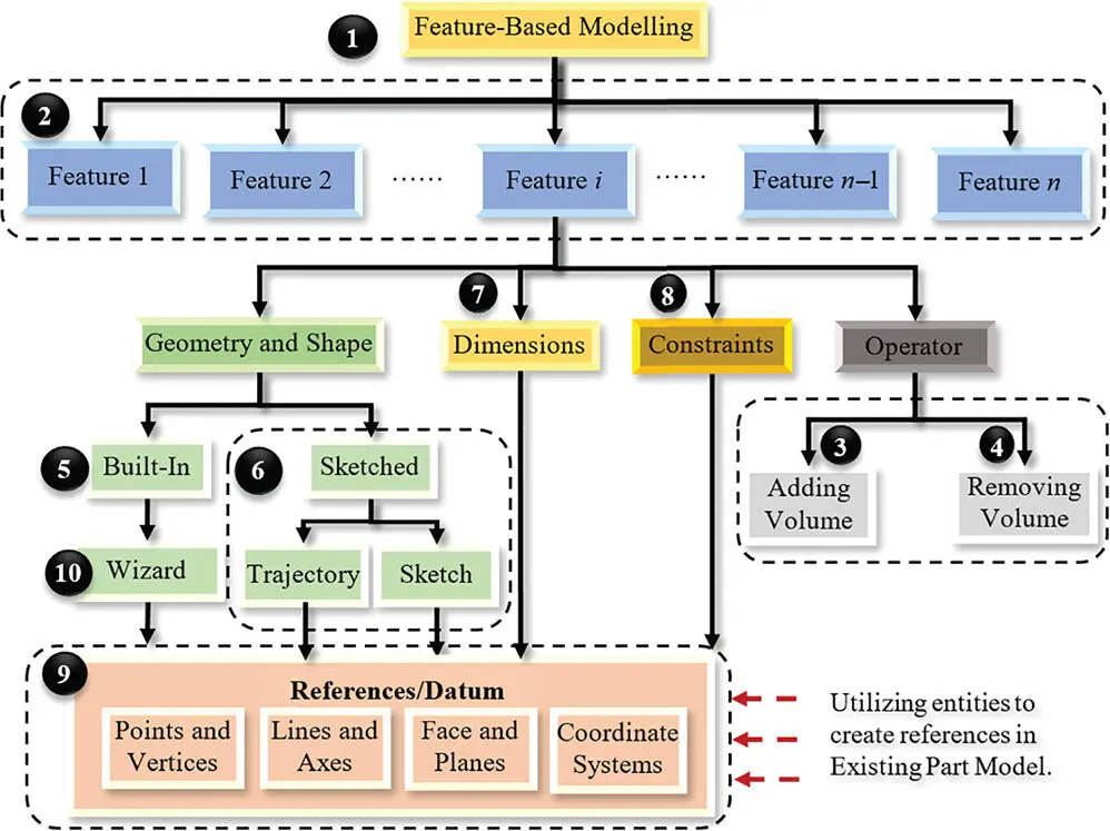
Figure 2.38Types of features in feature‐based modelling.
When an original CAD model of a part is available, any entities (edges, axes, surfaces, planes, or features) in the model can be identified and reused as the references to modify or create new features. Note that the information of any entity in the model is included and can be accessed through the model tree interfaces. Figure 2.39shows some major feature‐based modelling tools in SolidWorks. These tools are associated with the functional requirements to create and modify different types of features, as shown in Figure 2.38. Designers should be aware of these tools and know how to access them when they are needed.
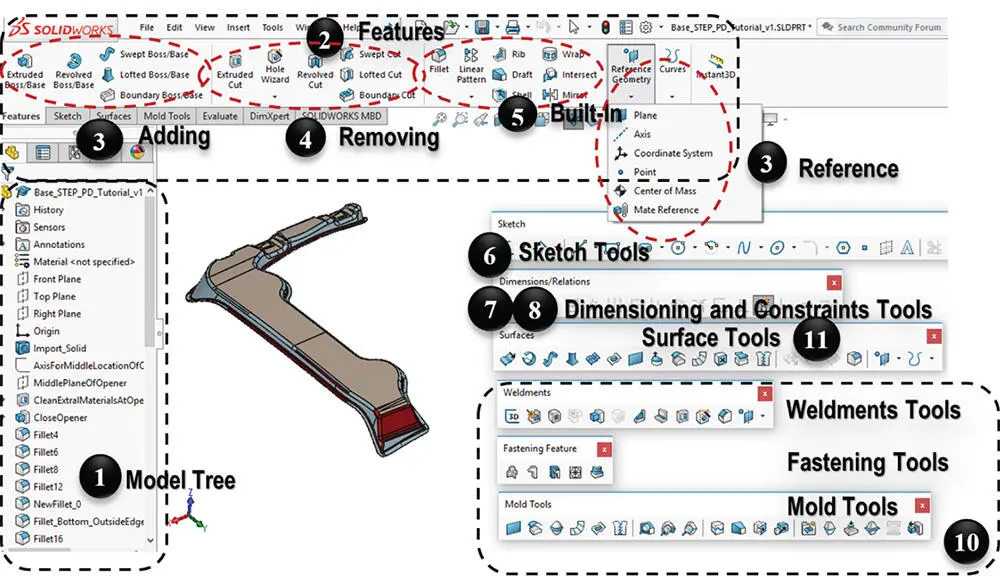
Figure 2.39Feature‐based modelling tools in SolidWorks.
Figure 2.40shows the procedure of modifying or creating a feature in a solid model. It begins with determination of design intent . Design intent represents the strategies to create a certain feature. For example, a cylindrical shape can be created by Extruding , Revolving , Lofting , or Sweeping , but the amount of information in creating a feature and the effort in modifying the feature are different from one another. The design intent is your selection of modelling technique when a number of modelling options are available. Multiple design intents might be involved for the same feature. Generally, a SolidWorks (SW) feature can either be a built‐in feature or a sketched feature . A built‐in feature, such as Fillet or Standard Hole , is created upon an existing feature, and all the required inputs are specified in the feature property window. A sketched feature , such as Extrusion , Sweep , or Revolve , requires the user to create one or more sketches to define the geometry and/or paths, and the rest of the inputs are defined in the feature property window. Revising or adding a feature in a complex part model with many free‐form boundary surfaces is not a trivial task. Designers are usually required to try different modelling strategies (for example, selecting and creating a sketch plane) to create a feature successfully.
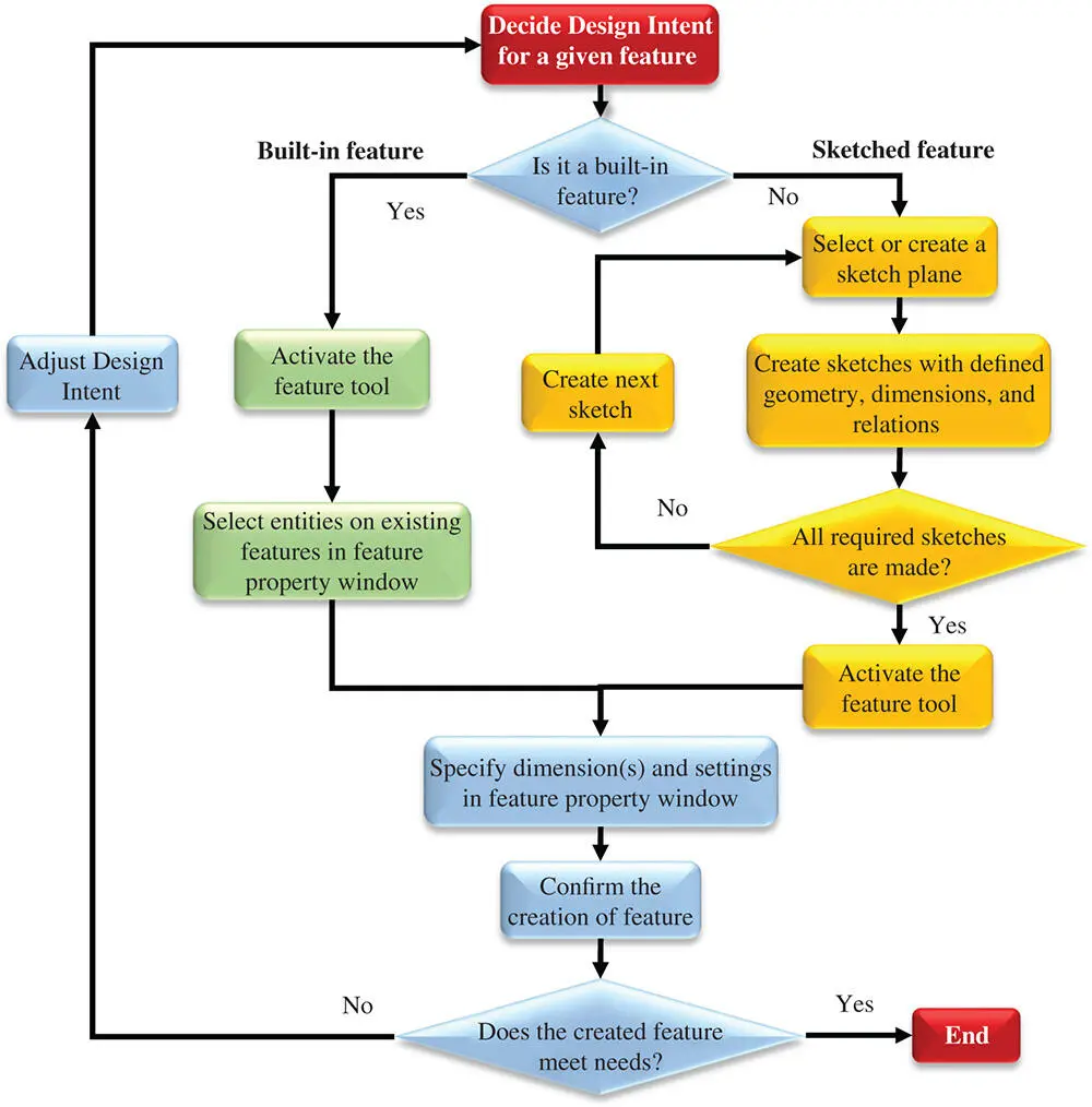
Figure 2.40Creating or modifying a feature in feature‐based modelling.
Figures 2.41and 2.42show two examples where a built‐in feature and a sketched feature are created, respectively.
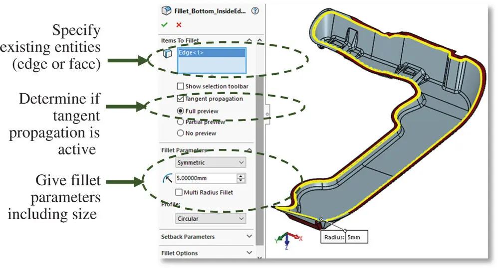
Figure 2.41Example of creating a built‐in feature.
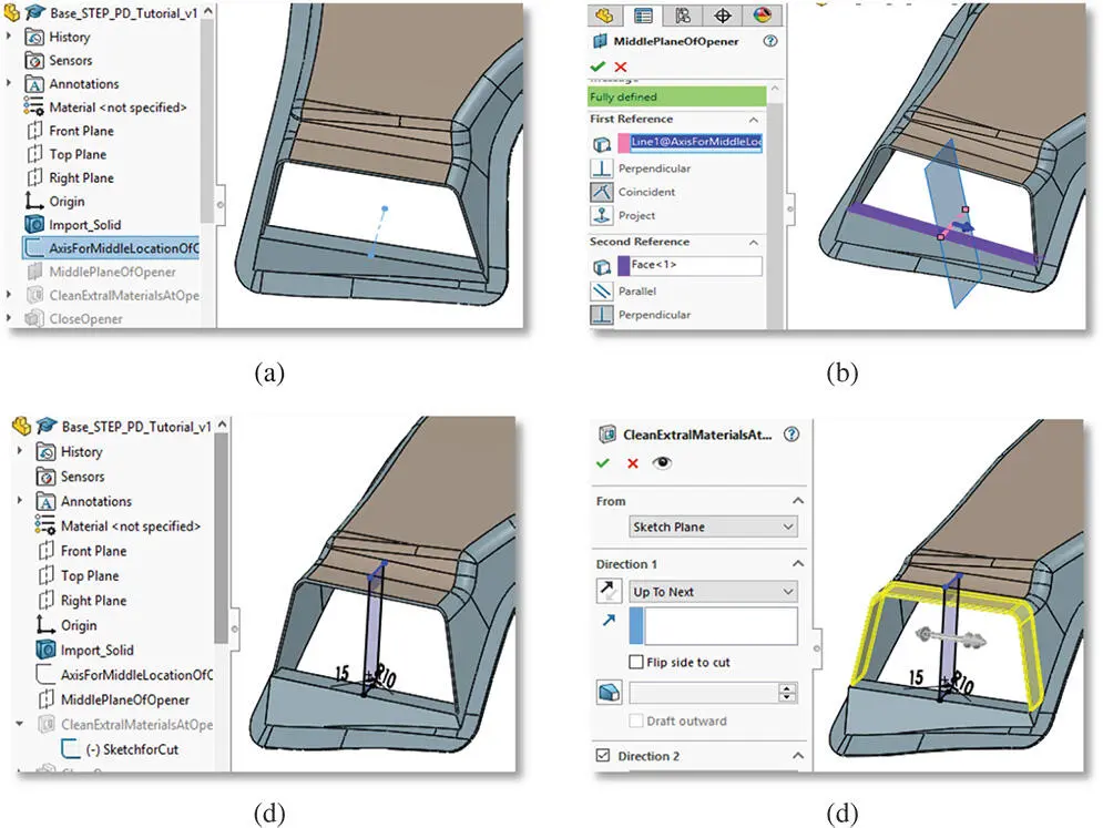
Figure 2.42Example of creating a sketched feature. (a) Create a reference axis. (b) Use an axis and a flat face to create a reference axis. (c) Create a sketch on a new plane. (d) Create an extrude cut at the outlet.
2.7 Summary
A solid object consists of (i) geometric elements at different levels, from vertices to edges, faces, volumes, and features, and (ii) the topological relations of geometric elements. Geometric modelling is used to create computer representations of solid objects, while geometric modelling lays the foundation for using computer aided techniques. The commonly used modelling methodologies include wireframe modelling, surface modelling, space decomposition, constructive solid geometric modelling, and feature‐based modelling.
The information of geometric representation of an object from different modelling methods may be different. A wireframe model consists entirely of points, lines, and curves; it does not have the information for face or volume, and no topological data are needed in modelling. A surface model stores the topological information in corresponding objects, but a surface model can still be ambiguous in some cases. Both a surface model and a solid model can be utilized to identify a shading area and a solid model has complete, valid, and unambiguous spatial addressability. In addition, a lower‐level model (i.e. a wireframe) can be extracted from a high‐level surface or solid model.
The same geometry can be modelled in different ways. However, it is desirable to take into consideration the design intents in geometric modelling. Design intent is beyond the size and shape of features and can be extended to manufacturing features such as tolerances, manufacturing processes, and design constraints. The use of design intents is an effective approach to build a parametric model of a part that is fully constrained and easy to modify. By far, feature‐based modelling is the most advanced method, where a part model is modelled as a set of features as well as their topological relations. Modern computer aided software tools support feature‐based modelling methods.
2.8 Modelling Problems
1 2.1 Create solid models for drawings with standard views (front, right, top, and isometric views) and annotated masses for the parts in Figure 2.43(unit: inch per pound; thickness: 0.25 inch; materials: grey iron). Figure 2.43Drawings for modelling Problem 2.1.
2 2.2 Create solid models for drawings with standard views (front, right, top, and isometric views) and annotated masses for the parts in Figure 2.44(unit: mm per gram; materials: grey iron). Figure 2.44Drawings for modelling Problem 2.2.
3 2.3 Create a pipe model with the dimensions specified in Figure 2.45. Have a few examples of design intents you incorporate in the modelling process and create a similar drawing to that in Figure 2.45with the answers about design intents and total mass in grams. Figure 2.45Drawing for modelling Problem 2.3.
References
1 Bi, Z.M. and Kang, B. (2014). Sensing and responding to the changes of geometric surfaces in flexible manufacturing and assembly. Enterprise Information Systems 8 (2): 225–245.
2 Bunge, M. (1983). Treatise on Basic Philosophy, Epistemology and Methodology I: Exploring the World, vol. 5. Dordrecht: D. Reidel Publishing Company.
Читать дальшеИнтервал:
Закладка:
Похожие книги на «Computer Aided Design and Manufacturing»
Представляем Вашему вниманию похожие книги на «Computer Aided Design and Manufacturing» списком для выбора. Мы отобрали схожую по названию и смыслу литературу в надежде предоставить читателям больше вариантов отыскать новые, интересные, ещё непрочитанные произведения.


Обсуждение, отзывы о книге «Computer Aided Design and Manufacturing» и просто собственные мнения читателей. Оставьте ваши комментарии, напишите, что Вы думаете о произведении, его смысле или главных героях. Укажите что конкретно понравилось, а что нет, и почему Вы так считаете.