Zhuming Bi - Computer Aided Design and Manufacturing
Здесь есть возможность читать онлайн «Zhuming Bi - Computer Aided Design and Manufacturing» — ознакомительный отрывок электронной книги совершенно бесплатно, а после прочтения отрывка купить полную версию. В некоторых случаях можно слушать аудио, скачать через торрент в формате fb2 и присутствует краткое содержание. Жанр: unrecognised, на английском языке. Описание произведения, (предисловие) а так же отзывы посетителей доступны на портале библиотеки ЛибКат.
- Название:Computer Aided Design and Manufacturing
- Автор:
- Жанр:
- Год:неизвестен
- ISBN:нет данных
- Рейтинг книги:3 / 5. Голосов: 1
-
Избранное:Добавить в избранное
- Отзывы:
-
Ваша оценка:
Computer Aided Design and Manufacturing: краткое содержание, описание и аннотация
Предлагаем к чтению аннотацию, описание, краткое содержание или предисловие (зависит от того, что написал сам автор книги «Computer Aided Design and Manufacturing»). Если вы не нашли необходимую информацию о книге — напишите в комментариях, мы постараемся отыскать её.
Computer Aided Design and Manufacturing being uniquely structured to classify and align engineering disciplines and computer aided technologies from the perspective of the design needs in whole product life cycles, utilizing a comprehensive Solidworks package (add-ins, toolbox, and library) to showcase the most critical functionalities of modern computer aided tools, and presenting real-world design projects and case studies so that readers can gain CAD and CAM problem-solving skills upon the CAD/CAM theory.
is an ideal textbook for undergraduate and graduate students in mechanical engineering, manufacturing engineering, and industrial engineering. It can also be used as a technical reference for researchers and engineers in mechanical and manufacturing engineering or computer-aided technologies.
Computer Aided Design and Manufacturing — читать онлайн ознакомительный отрывок
Ниже представлен текст книги, разбитый по страницам. Система сохранения места последней прочитанной страницы, позволяет с удобством читать онлайн бесплатно книгу «Computer Aided Design and Manufacturing», без необходимости каждый раз заново искать на чём Вы остановились. Поставьте закладку, и сможете в любой момент перейти на страницу, на которой закончили чтение.
Интервал:
Закладка:
In the numerical simulations, the finite volume of solid is decomposed into small cells, so‐called isomorphic cells ; these cells are usually smaller by several orders of magnitude than the dimensions of the solid itself. The space decomposition in a numerical simulation is also called a meshing process and Figure 2.28shows two example models where the solids are decomposed into a set of small cells called elements.
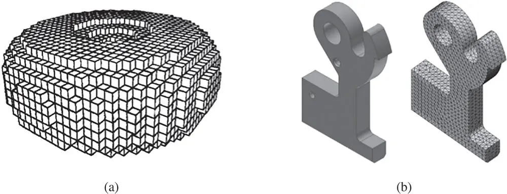
Figure 2.28Examples of space decomposition in numerical simulation. (a) Solid A. (b) Solid B.
2.4.5 Solid Modelling
In solid modelling, the geometry of an object is modelled by a set of solid primitives, which are assembled into an object using composition operations. The modelling procedure to combine elemental solids using composition operations is commonly known as Constructive Solid Geometry (CSG) modelling. The geometric representation from solid modelling gives complete information about physical objects. CSG modelling is based on the following assumptions:
1 A constitutive object is a rigid solid; the object has a concrete and invariant shape not affected by spatial location or position.
2 An object fills the space occupied by it homogeneously; the inside positions of the object are always connected to the complementary of the model through boundary surfaces.
3 The extension of an object is finite; the model can be mapped to a 2D plan for computer visualization.
4 An object can be generated as a composition of a finite number of solid primitives and the modelled object model can be stored in a computer.
5 An object can be modelled as a closed set in terms of rigid solid motions.
2.4.5.1 Solid Primitives
Solid primitives are the simplest solids used in CSG. As shown in Figure 2.29, most commonly used primitives include cuboids , cylinders , prisms , spheres , cones , and tori . Note that different solid modelling tools may use different solid primitives in CSG.
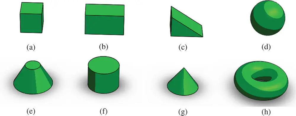
Figure 2.29Examples of solid primitives. (a) Cuboid. (b) Rectangle cuboid. (c) Prism. (d) Sphere. (e) Tapped cylinder. (f) Cylinder. (g) Cone. (h) Torus.
For an object with a complex geometry, solid primitives can be customized. Table 2.11lists some common methods used to create solid primitives (i.e. design features) in a solid modelling tool. These modelling tools include extruding , revolving , sweeping , lofting , and many others.
Table 2.11Modelling tools for customized solid primitives.
| Modelling tool | Explanation | Example |
| Extruding | Extruding creates a solid by moving a two‐dimensional profile along a straight path. | 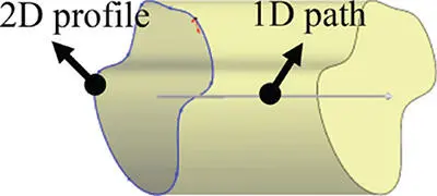 |
| Revolving | Revolving creates a solid by revolving a two‐dimensional profile along an axis. | 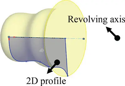 |
| Sweeping | Sweeping creates a solid by translating a 2D profile along a 3D path with or without one or a few of 3D guide curves. | 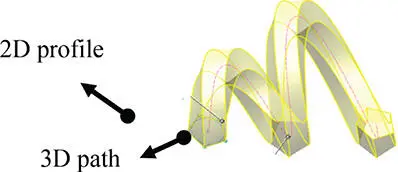 |
| Lofting | Lofting creates a solid by specifying and connecting vertices on a series of 2D profiles. | 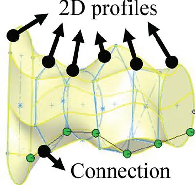 |
2.4.5.2 Composition Operations
In CSG, an object is constructed from solid primitives by composition operations. Eligible composition operations are the Boolean operations on sets, i.e. union (∪), intersection (∩), and difference (\), as well as associated geometric transformations of those sets.
For a pair of solid primitives with given postures, different composition operations lead to different outcomes of assembled objects. Figure 2.30shows three different objects from the compositions of a rectangular cuboid and a cylinder primitive.
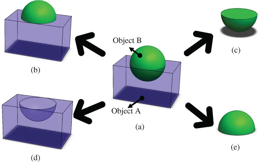
Figure 2.30Differences of Boolean operations. (a) Two primitives at given positions. (b) A∪B. (c) A∩B. (d) A\B. (e) B\A.
Other than the Boolean operations among solid primitives, a coordinate transformation can be applied to individual primitives before a Boolean operation takes place. Common operations of coordinate transformation include translating , copying , rotating , mirroring , and scaling . Figure 2.31shows some examples of these operations.
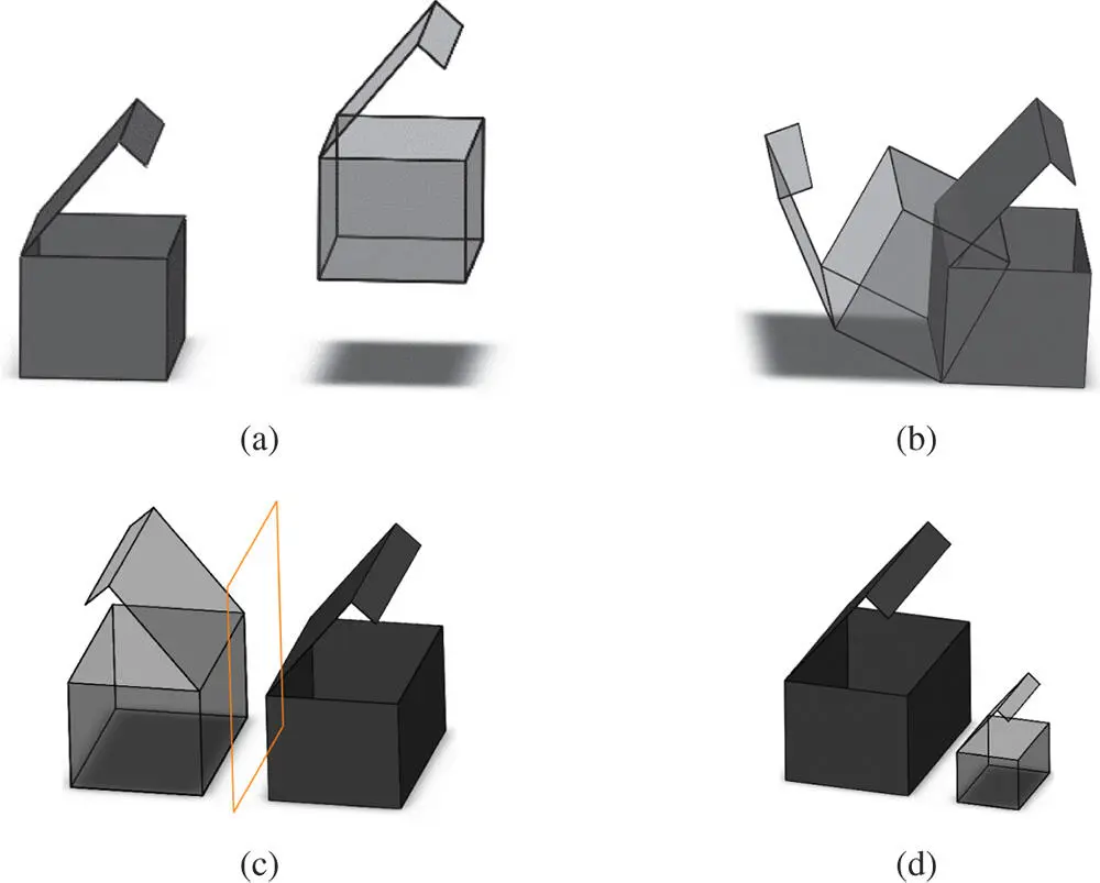
Figure 2.31Common operations of coordinate transformation. (a) Translating. (b) Rotating. (c) Mirroring. (d) Scaling.
2.4.5.3 CSG Modelling
Two basic elements of a solid model are (i) elemental geometric solids T i( i = 1, 2, 3, …, N ), where N is the number of available solid primitives of the object, and (ii) the set of composition operations ⊗ for a Boolean operation (‘∪’, ‘∩’, or ‘\’) of geometric solids.
A series of composition operations can be expressed as
(2.19) 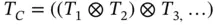
where T Cstands for the assembled object, T i( i = 1, 2, 3, …, N ) are the primitives in the object, and ⊗ is one of the Boolean operations (‘∪’, ‘∩’, and ‘\’).
2.4.5.4 Modelling Procedure
The procedure of CSG modelling is as follows:
1 Define a set of solid primitives.
2 Create dimensional variables and constraints of solid primitives.
3 Transform each solid primitive into the appropriate position, applying the generalized set operations.
4 Finally, combine elemental solids to generate a unique and legal solid model.
The above procedure shows that the resulting solid model is affected by (i) the set of solid primitives and dimensions, (ii) locations and orientations of solid primitives, and (iii) the types and orders of the Boolean operations of solid primitives. Figure 2.32shows different solid models from the same set of solid primitives.
Figure 2.32Different solid models from the same set of solid primitives.
Читать дальшеИнтервал:
Закладка:
Похожие книги на «Computer Aided Design and Manufacturing»
Представляем Вашему вниманию похожие книги на «Computer Aided Design and Manufacturing» списком для выбора. Мы отобрали схожую по названию и смыслу литературу в надежде предоставить читателям больше вариантов отыскать новые, интересные, ещё непрочитанные произведения.


Обсуждение, отзывы о книге «Computer Aided Design and Manufacturing» и просто собственные мнения читателей. Оставьте ваши комментарии, напишите, что Вы думаете о произведении, его смысле или главных героях. Укажите что конкретно понравилось, а что нет, и почему Вы так считаете.