Zhuming Bi - Computer Aided Design and Manufacturing
Здесь есть возможность читать онлайн «Zhuming Bi - Computer Aided Design and Manufacturing» — ознакомительный отрывок электронной книги совершенно бесплатно, а после прочтения отрывка купить полную версию. В некоторых случаях можно слушать аудио, скачать через торрент в формате fb2 и присутствует краткое содержание. Жанр: unrecognised, на английском языке. Описание произведения, (предисловие) а так же отзывы посетителей доступны на портале библиотеки ЛибКат.
- Название:Computer Aided Design and Manufacturing
- Автор:
- Жанр:
- Год:неизвестен
- ISBN:нет данных
- Рейтинг книги:3 / 5. Голосов: 1
-
Избранное:Добавить в избранное
- Отзывы:
-
Ваша оценка:
Computer Aided Design and Manufacturing: краткое содержание, описание и аннотация
Предлагаем к чтению аннотацию, описание, краткое содержание или предисловие (зависит от того, что написал сам автор книги «Computer Aided Design and Manufacturing»). Если вы не нашли необходимую информацию о книге — напишите в комментариях, мы постараемся отыскать её.
Computer Aided Design and Manufacturing being uniquely structured to classify and align engineering disciplines and computer aided technologies from the perspective of the design needs in whole product life cycles, utilizing a comprehensive Solidworks package (add-ins, toolbox, and library) to showcase the most critical functionalities of modern computer aided tools, and presenting real-world design projects and case studies so that readers can gain CAD and CAM problem-solving skills upon the CAD/CAM theory.
is an ideal textbook for undergraduate and graduate students in mechanical engineering, manufacturing engineering, and industrial engineering. It can also be used as a technical reference for researchers and engineers in mechanical and manufacturing engineering or computer-aided technologies.
Computer Aided Design and Manufacturing — читать онлайн ознакомительный отрывок
Ниже представлен текст книги, разбитый по страницам. Система сохранения места последней прочитанной страницы, позволяет с удобством читать онлайн бесплатно книгу «Computer Aided Design and Manufacturing», без необходимости каждый раз заново искать на чём Вы остановились. Поставьте закладку, и сможете в любой момент перейти на страницу, на которой закончили чтение.
Интервал:
Закладка:
2.4.5.5 Data Structure of CSG Models
Figure 2.32shows that a CSG model consists of geometric and topological data, which is similar to a model from the B‐Rep modelling process. A data structure of a CSG model does not give the model shape directly; instead, it consists of a number of solid primitives and combines them through a procedural description. More specifically, the data structure corresponds to a graph and tree as the history of applying the Boolean operations on solid primitives, in such a way that:
1 The topological information is stored in a binary tree format.
2 The outer leaf nodes correspond to solid primitives.
3 The interior nodes are the Boolean operations over solid primitives or components.
Figure 2.33shows the data structure of an example CSG model. It consists of two data types: (i) three solid primitives, i.e. two blocks with different dimensions and one cylinder, and (ii) a topological tree, i.e. one union operation of two blocks and then one difference operation of the united component with the cylinder.
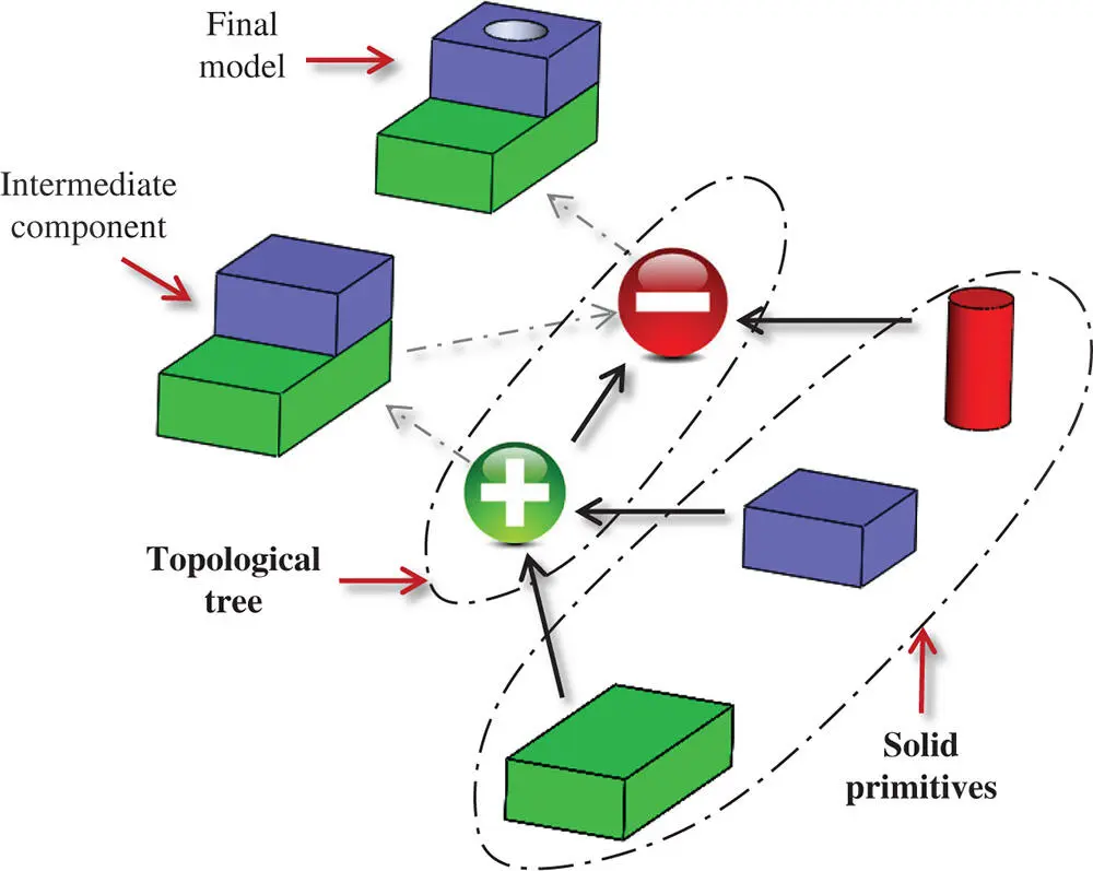
Figure 2.33Data structure example of a CSG model.
Since CSG modelling begins with solid primitives, CSG models are always valid and they have complete and unambiguous information of solids. In addition, the primitives are defined directly at the volume level and low‐level entities such as vertices, edges, and faces are defined implicitly. However, an entity at any level of solid can be utilized and accessed readily when it is needed. The advantages of CSG modelling are:
1 It constructs a solid model with the minimized steps.
2 It leads to a concise database with less storage since the entities at the low level are represented implicitly.
3 It provides a complete history of the model, which is retained but can be altered at any phase of product design.
4 A CSG model can be easily converted to the corresponding boundary representation.
The tools for CSG modelling were introduced in the 1980s. However, early CSG modelling tools suffered from a number of limitations as follows:
1 They can only provide far fewer types of basic solid primitives in modelling than the vast number of varieties that would be required in engineering practice.
2 CSG modelling does not adequately support engineering thinking. It implies that a final solid model is created from a theoretical sketch through continued modifications. In other words, traditional CSG modelling is rather used to reconstruct solid models than to actually design.
3 CSG modelling does not provide a comprehensive description of solids to be modelled. Early CSG models do not cover the information on microgeometry, materials, and physical characteristics. All of the above are important for operation, manufacturing, and control of products.
2.5 Feature‐Based Modelling with Design Intents
There are numerous ways to create computer models using a given geometry. However, geometry and shape of an object have their purpose in a product and it is very helpful for a designer to take design intent into account when creating computer representations of solids.
Design intent is a term used to describe how the model should be created and how it should behave when it is changed. Design intent should be built into the model according to how dimensions and relations are established, since changes to a model will yield a different result for each different design intent.
Design intent is not just about the size and shape of features, but it can be extended to cover tolerances , manufacturing processes , design constraints , and relationships of features and dimensions . The use of design intents is an effective approach to build a parametric model of a part that is fully constrained and easy for modification. For example, sketches can be dimensioned to reflect design intents in parametric modelling. If the design intents for the part have not been adequately considered, the model might be useless from a practical viewpoint (Rynne 2006).
With regards to design changes, geometric features created at the design phase are closely related to manufacturing activities at other phases of a product cycle. It is ideal that designers are able to model solids directly with expected features. The advancement of computer aided methods in Figure 2.34shows the growing expectation of the functional requirements (FRs) on computer aided technologies, which is from two‐dimensional drafting and drawing to high‐level solid modelling with consideration of design intents.

Figure 2.34From 2D drafting and drawing to interactive solid modelling with design intents.
Feature‐based modelling refers to the construction of object geometry as a combination of form features with design intents. The designer specifies the features in engineering terms, such as holes, slots, or bosses, rather than in geometric terms, such as circles or boxes. The concepts of features can also be extended to include non‐graphic information. This information can be used in activities such as drafting, numerical control (NC), finite‐element analysis, and kinematic analysis. Furthermore, feature‐based packages frequently record the geometric construction and modification sequences used in building the model.
Bunge (1983) gave the principles of feature‐based modelling as:
1 The physical world consists of things that are considered to be objects regardless of their contents. Objects can be characterized by their features, known or to be detected by scientific instruments. Features are quality and quantity characteristics, together with the correlations between them.
2 In terms of design, products and their various parts can be interpreted as objects, while features are characteristics associated with them. Relations between characteristics are described and regulated by correlations and restrictions.
3 As regards mechanical products, the geometric form is of primary importance in respect of material realization; therefore, it seems to be natural that the geometry of objects is derived from given features and their relations.
Features in an object can be defined by three aspects: (i) the characteristics of geometric shape, (ii) the characteristics of processes, and (iii) the ontological interpretation for the meanings of features. Figure 2.35shows an example of a machined part with some geometric features with logical associations of points, edges, and surfaces of the part. Figure 2.36shows an example of classified manufacturing features for prismatic parts by Šibalija et al. (2013), while Figure 2.37shows a few exemplified parts in a chair model with their ontological features.
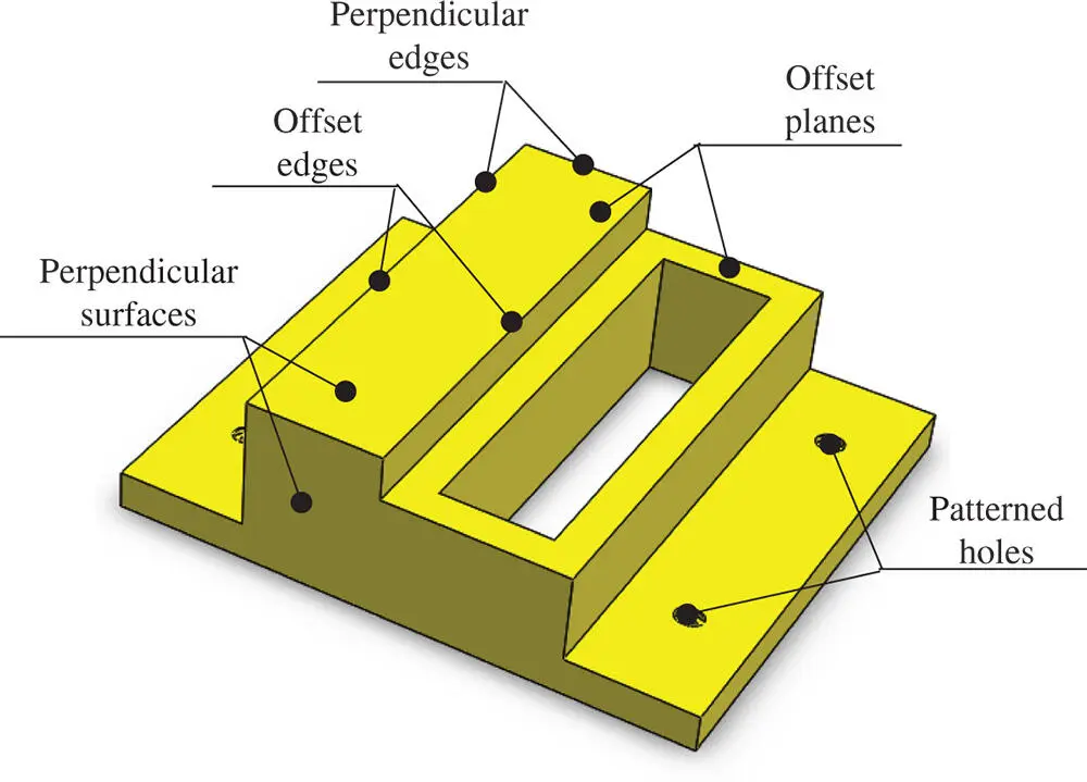
Figure 2.35Example of geometric features.
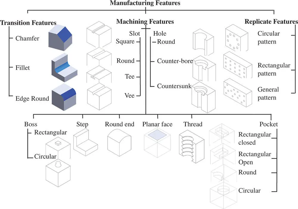
Figure 2.36Classified manufacturing features for prismatic parts (Šibalija et al. 2013).
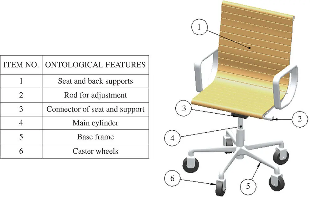
Figure 2.37Examples of ontological features in a chair model.
Читать дальшеИнтервал:
Закладка:
Похожие книги на «Computer Aided Design and Manufacturing»
Представляем Вашему вниманию похожие книги на «Computer Aided Design and Manufacturing» списком для выбора. Мы отобрали схожую по названию и смыслу литературу в надежде предоставить читателям больше вариантов отыскать новые, интересные, ещё непрочитанные произведения.


Обсуждение, отзывы о книге «Computer Aided Design and Manufacturing» и просто собственные мнения читателей. Оставьте ваши комментарии, напишите, что Вы думаете о произведении, его смысле или главных героях. Укажите что конкретно понравилось, а что нет, и почему Вы так считаете.