Zhuming Bi - Computer Aided Design and Manufacturing
Здесь есть возможность читать онлайн «Zhuming Bi - Computer Aided Design and Manufacturing» — ознакомительный отрывок электронной книги совершенно бесплатно, а после прочтения отрывка купить полную версию. В некоторых случаях можно слушать аудио, скачать через торрент в формате fb2 и присутствует краткое содержание. Жанр: unrecognised, на английском языке. Описание произведения, (предисловие) а так же отзывы посетителей доступны на портале библиотеки ЛибКат.
- Название:Computer Aided Design and Manufacturing
- Автор:
- Жанр:
- Год:неизвестен
- ISBN:нет данных
- Рейтинг книги:3 / 5. Голосов: 1
-
Избранное:Добавить в избранное
- Отзывы:
-
Ваша оценка:
Computer Aided Design and Manufacturing: краткое содержание, описание и аннотация
Предлагаем к чтению аннотацию, описание, краткое содержание или предисловие (зависит от того, что написал сам автор книги «Computer Aided Design and Manufacturing»). Если вы не нашли необходимую информацию о книге — напишите в комментариях, мы постараемся отыскать её.
Computer Aided Design and Manufacturing being uniquely structured to classify and align engineering disciplines and computer aided technologies from the perspective of the design needs in whole product life cycles, utilizing a comprehensive Solidworks package (add-ins, toolbox, and library) to showcase the most critical functionalities of modern computer aided tools, and presenting real-world design projects and case studies so that readers can gain CAD and CAM problem-solving skills upon the CAD/CAM theory.
is an ideal textbook for undergraduate and graduate students in mechanical engineering, manufacturing engineering, and industrial engineering. It can also be used as a technical reference for researchers and engineers in mechanical and manufacturing engineering or computer-aided technologies.
Computer Aided Design and Manufacturing — читать онлайн ознакомительный отрывок
Ниже представлен текст книги, разбитый по страницам. Система сохранения места последней прочитанной страницы, позволяет с удобством читать онлайн бесплатно книгу «Computer Aided Design and Manufacturing», без необходимости каждый раз заново искать на чём Вы остановились. Поставьте закладку, и сможете в любой момент перейти на страницу, на которой закончили чтение.
Интервал:
Закладка:
As shown in the middle three columns of Table 2.7, the numbers of faces ( F ), edges ( E ), and vertices ( V ) are counted and the valid condition for a simple solid using the Euler–Poincare Law is applied. It shows that all objects satisfy the conditions as simple objects.
Example 2.6
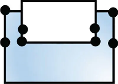
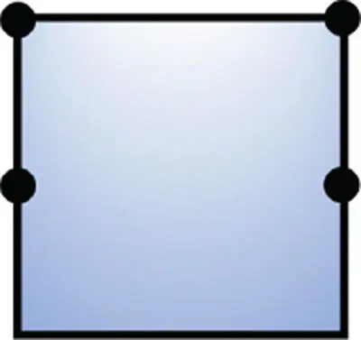
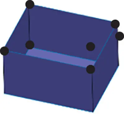
To use the Euler–Poincare Law to justify the validity of open objects in the first column of Table 2.8.
Table 2.8Examples of open objects.
| Example | F | E | V | L | B | G | F − E + V − L = B − G |
 |
0 | 1 | 2 | 0 | 1 | 0 | 0 − 1 + 2–0 ≡ 1 − 0 |
 |
0 | 3 | 4 | 0 | 1 | 0 | 0 − 3 + 4 − 0 ≡ 1 − 0 |
 |
2 | 8 | 8 | 1 | 1 | 0 | 2 − 8 + 8 − 1 ≡ 1 − 0 |
 |
2 | 2 | 2 | 1 | 1 | 0 | 2 − 2 + 2 − 1 ≡ 1 − 0 |
 |
1 | 4 | 4 | 0 | 1 | 0 | 1 − 4 + 4 − 0 ≡ 1 − 0 |
 |
5 | 12 | 8 | 0 | 1 | 0 | 5 − 12 + 8 − 0 ≡ 1 − 0 |
Solution
As shown in the middle six columns of Table 2.8, the number of faces ( F ), edges ( E ), vertices ( V ), bodies ( B ), inner loops on faces ( L ), and genuses ( G ) in a geometry is counted and the valid condition for a simple solid by the Euler–Poincare Law is applied. It shows that all of the objects satisfy the conditions as open objects.
Example 2.7
To use the Euler–Poincare law to justify the validity of generic objects in the first column of Table 2.9.
Table 2.9Examples of generic objects.
| Example | F | E | V | L | B | G | F − E + V − L = 2( B − G ) |
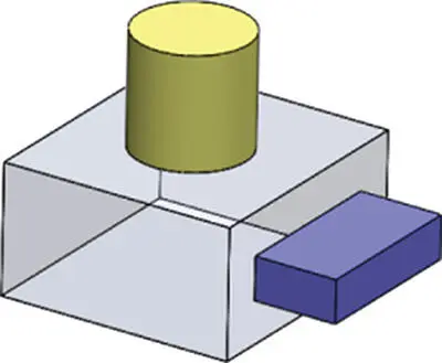 |
13 | 27 | 18 | 2 | 1 | 0 | 13 − 27 + 18 − 2 ≡ 2(1 − 0) |
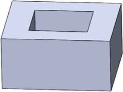 |
10 | 24 | 16 | 2 | 1 | 1 | 10 − 24 + 16 − 2 ≡ 2(1 − 1) |
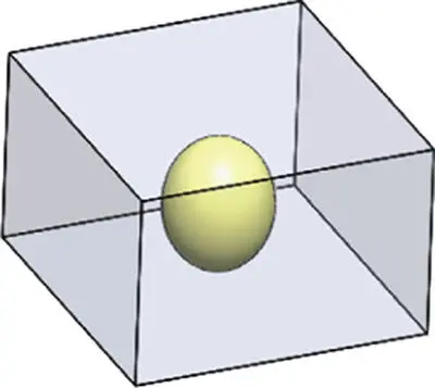 |
7 | 13 | 10 | 0 | 2 | 0 | 7 − 13 + 10 − 0 ≡ 2(2 − 0) |
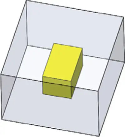 |
12 | 24 | 16 | 0 | 2 | 0 | 12 − 24 + 16 − 0 ≡ 2(2 − 0) |
Solution
As shown in the middle six columns of Table 2.9, the numbers of faces ( F ), edges ( E ), vertices ( V ), bodies ( B ), inner loops on faces ( L ), and genuses ( G ) in a geometry are counted and the valid condition for a simple solid using the Euler–Poincare Law is applied. It shows that all generic objects satisfy the conditions as generic objects.
2.3.3 Euler–Poincare Law for Solids
Objects in the physical world are solid. A solid object consists of solid elements and the process of adding, merging, uniting, or deleting solid elements in a solid object is commonly called Euler operation . To sustain a valid solid object, the second condition in the Euler–Poincare Law, which is usually called the Euler formula ( F − E + V = 2), must be satisfied. This leads to the following features of a solid object:
1 Each vertex must have at least three edges to meet together
2 Each edge must be shared by two and only two faces.
3 Any face must be homomorphic to a disk with no holes; it is simply connected and bounded by a single ring of edges.
4 A solid must be simply connected with no through hole.
2.4 Basic Modelling Methods
The methods of geometric modelling differ from one to another based on the level of information completeness of the features in objects. Figure 2.22shows the evolution of modelling methods. Wireframe modelling is historically developed for computer aided drawing but only for the representation of key vertices and boundary edges. Solid modelling is the most advanced modelling technique since it is capable of representing the complete information of solids and beyond. Other methods such as surface modelling , boundary surface modelling (also called B‐Rep or Mantle modelling ), and space decomposition are between the extremes of wireframe modelling and solid modelling in terms of the completeness of information about solids.
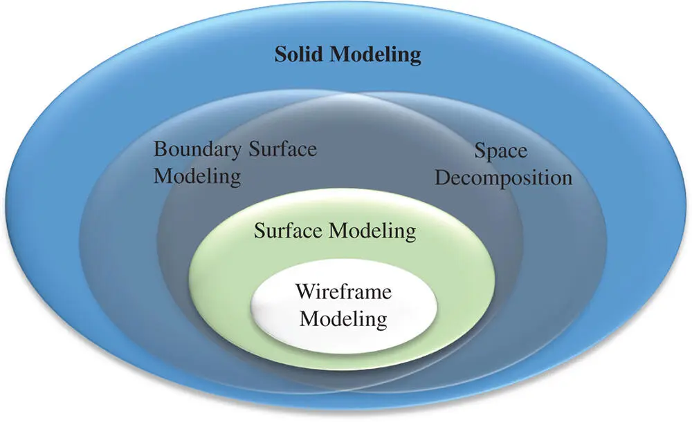
Figure 2.22Variety of geometric modelling methods.
2.4.1 Wireframe Modelling
A wireframe model represents the boundary edges of an object; these edges can be of lines, arcs, and curves. A wireframe model does not include the upper‐level information such as boundary surfaces or volumes. In addition, the results from wireframe modelling have the following limitations:
All of the edges are displayed as elements in an image and the visibility caused by overlapping is not identifiable.
No high‐level information related to solids and masses such as surface areas or masses is available.
The primary data from wireframe modelling is the coordinates of vertices; therefore, the preparation, importing, and processing of modelling data are very time‐consuming and error‐prone.
The wireframe modelling method is incapable of designing shapes and specifying more complex forms due to the need for a large number of data points.
In addition, due to incompleteness of solid information, a wireframe model may cause the ambiguity of a represented geometry. Figure 2.23shows two examples whose wireframe models in the left column are not able to distinguish the actual geometrics of objects since their corresponding wireframe models are the same.
Читать дальшеИнтервал:
Закладка:
Похожие книги на «Computer Aided Design and Manufacturing»
Представляем Вашему вниманию похожие книги на «Computer Aided Design and Manufacturing» списком для выбора. Мы отобрали схожую по названию и смыслу литературу в надежде предоставить читателям больше вариантов отыскать новые, интересные, ещё непрочитанные произведения.


Обсуждение, отзывы о книге «Computer Aided Design and Manufacturing» и просто собственные мнения читателей. Оставьте ваши комментарии, напишите, что Вы думаете о произведении, его смысле или главных героях. Укажите что конкретно понравилось, а что нет, и почему Вы так считаете.