Mohinder S. Grewal - Global Navigation Satellite Systems, Inertial Navigation, and Integration
Здесь есть возможность читать онлайн «Mohinder S. Grewal - Global Navigation Satellite Systems, Inertial Navigation, and Integration» — ознакомительный отрывок электронной книги совершенно бесплатно, а после прочтения отрывка купить полную версию. В некоторых случаях можно слушать аудио, скачать через торрент в формате fb2 и присутствует краткое содержание. Жанр: unrecognised, на английском языке. Описание произведения, (предисловие) а так же отзывы посетителей доступны на портале библиотеки ЛибКат.

- Название:Global Navigation Satellite Systems, Inertial Navigation, and Integration
- Автор:
- Жанр:
- Год:неизвестен
- ISBN:нет данных
- Рейтинг книги:4 / 5. Голосов: 1
-
Избранное:Добавить в избранное
- Отзывы:
-
Ваша оценка:
Global Navigation Satellite Systems, Inertial Navigation, and Integration: краткое содержание, описание и аннотация
Предлагаем к чтению аннотацию, описание, краткое содержание или предисловие (зависит от того, что написал сам автор книги «Global Navigation Satellite Systems, Inertial Navigation, and Integration»). Если вы не нашли необходимую информацию о книге — напишите в комментариях, мы постараемся отыскать её.
GNSSs including GPS, Glonass, Galileo, BeiDou, QZSS, and IRNSS/NAViC,
and MATLAB programs on square root information filtering (SRIF)
This book provides readers with solutions to real-world problems associated with global navigation satellite systems, inertial navigation, and integration. It presents readers with numerous detailed examples and practice problems, including GNSS-aided INS, modeling of gyros and accelerometers, and SBAS and GBAS. This revised fourth edition adds new material on GPS III and RAIM. It also provides updated information on low cost sensors such as MEMS, as well as GLONASS, Galileo, BeiDou, QZSS, and IRNSS/NAViC, and QZSS. Revisions also include added material on the more numerically stable square-root information filter (SRIF) with MATLAB programs and examples from GNSS system state filters such as ensemble time filter with square-root covariance filter (SRCF) of Bierman and Thornton and SigmaRho filter.
Global Navigation Satellite Systems, Inertial Navigation, and Integration, 4th Edition Updates on the significant upgrades in existing GNSS systems, and on other systems currently under advanced development Expanded coverage of basic principles of antenna design, and practical antenna design solutions More information on basic principles of receiver design, and an update of the foundations for code and carrier acquisition and tracking within a GNSS receiver Examples demonstrating independence of Kalman filtering from probability density functions of error sources beyond their means and covariances New coverage of inertial navigation to cover recent technology developments and the mathematical models and methods used in its implementation Wider coverage of GNSS/INS integration, including derivation of a unified GNSS/INS integration model, its MATLAB implementations, and performance evaluation under simulated dynamic conditions
is intended for people who need a working knowledge of Global Navigation Satellite Systems (GNSS), Inertial Navigation Systems (INS), and the Kalman filtering models and methods used in their integration.
Global Navigation Satellite Systems, Inertial Navigation, and Integration — читать онлайн ознакомительный отрывок
Ниже представлен текст книги, разбитый по страницам. Система сохранения места последней прочитанной страницы, позволяет с удобством читать онлайн бесплатно книгу «Global Navigation Satellite Systems, Inertial Navigation, and Integration», без необходимости каждый раз заново искать на чём Вы остановились. Поставьте закладку, и сможете в любой момент перейти на страницу, на которой закончили чтение.
Интервал:
Закладка:
Hemispherical Resonator Gyroscopes
These are also called wine glass gyroscopes , referring to resonant modes of wine glass rims, the nodes of which move when the wine glass is rotated about its stem – caused by Coriolis coupling. These devices can continue to operate through short‐term radiation events when electronic devices are shut down.
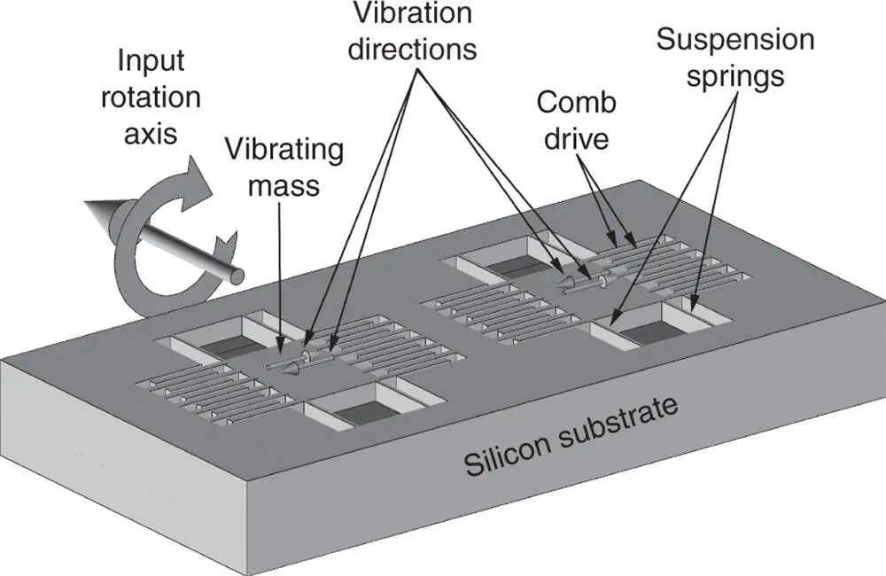
Figure 3.4MEMS tuning fork gyroscope.
3.3.1.3 Optical Gyroscopes (RLGs and FOGs)
There are two essential designs for optical gyroscopes, both of which depend on the Sagnac effect , a phenomenon studied by Franz Harress in 1911 [6] and Georges Sagnac in 1913. The effect has to do with the relative delay of two light beams from the same source traveling in opposite directions around the same closed loop, and how their relative delay depends on the rotation rate of the apparatus in the plane of the loop. The effect has been named for Sagnac, who showed that the delay difference was proportional to the rotation rate, and the effect scaled as the area of the loop. The effect was not used for sensing rotation until after a working laser was demonstrated in 1960, first with the lasing cavity in the closed optical path – the ring laser gyroscope (RLG) – and later using a kilometers‐long coil of optical fiber – the fiber optic gyroscope (FOG).
Ring laser gyroscopes are rate integrating gyroscopes. Their output interferometric phase rate is proportional to rotation rate, so each output phase shift represents an incremental inertial angular rotation angle. To minimize temperature and pressure sensitivities, their closed‐loop optical paths are typically machined into very stable materials. Early designs exhibited a “lock‐in” problem near zero input rates, due to backscatter off the mirrors. Later designs avoided this by using out‐of‐plane optical paths and multi‐frequency lasing cavities.
Fiber optic gyroscopes were first developed after single‐mode optical fibers became available, about a decade after the first laser. Unlike RLGs, FOGs are rate gyros. Their output is proportional to the input rotation rate, and must be integrated to get rotation angles. The optical loop in this case is a very long coil of optical fiber with an external laser source.
3.3.2 Accelerometers
Accelerometers used in inertial navigation measure the force required to keep a proof mass stationary with respect to its enclosure, which is called specific force to distinguish it from unsensed gravitational accelerations. Accelerometer designs differ in how that force is measured, and how that force is distributed. Examples of these different design approaches are given in the following text.
3.3.2.1 Mass‐spring Designs
These measure stress in the material connecting the proof mass to its enclosure. A spring scale measures the strain in a spring, which is proportional to the force (stress) applied. Similar designs use other means to measure that stress:
Beam accelerometers sense the surface tension on a supporting beam surface to measure the load normal to the beam surface due to applied specific force.
Piezoresistive accelerometers use the change in resistance in the stressed support material. MEMS accelerometers used for automotive air bag deployment have used piezoresistance.
Piezoelectric accelerometers have long been used for measuring vibrational acceleration, and have been used as essentially DC sensors in piezoelectric capacitors on MEMS beam accelerometers.
SAW (surface acoustic wave) accelerometers use strain‐induced shifts in the frequency of surface SAW resonators as a measure of the strain in the support material (a beam, for example).
Vibrating wire accelerometers use the frequency change in vibrating support wires due to changes in tension (stress) in the wires to measure the force applied by the wire to the supported proof mass. Because the fundamental vibration frequency of a wire under tension varies as the square root of tension, these are not linear sensors.
… and there are many more.
3.3.2.2 Pendulous Integrating Gyroscopic Accelerometers (PIGA)
This was the first “inertial grade” accelerometer (see Section 1.3.2.2), and is still in use today for high‐end applications such as ICBM navigation during launch.
3.3.2.3 Electromagnetic
Force‐rebalance . A common design for electromagnetic accelerometers uses permanent magnets as part of the proof mass, surrounded by a voice coil used to keep the magnet in a fixed position. The current required in the coil to keep it there will then be proportional to the force applied.
Inductive designs . A drag cup is a non‐magnetic conducting cylindrical sleeve with a rotating bar magnet inside, so that the axial torque on the drag cup will be proportional to the rotation rate of the magnet. Analog automobile tachometers and speedometers use them with a torsion spring on the drag cup to indicate rpms or speed. They have also been used with mass‐unbalanced drag cups such that the magnet rotation rate required to keep the drag cup stationary in an accelerating environment is proportional to acceleration and each revolution of the magnet represents an increment in velocity – making it an integrating accelerometer. Two of these can also be concatenated together in series such that they also integrate velocity to get position. Although they have performed well as tachometers and speedometers, they have not yet been sufficiently accurate for inertial navigation.
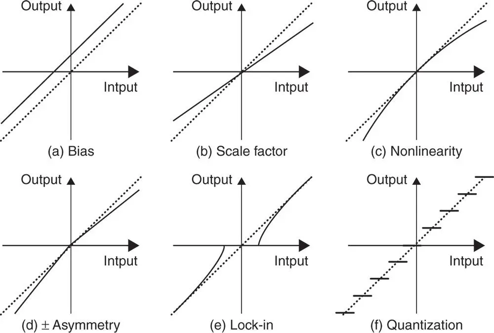
Figure 3.5Common input–output error types.
3.3.2.4 Electrostatic
The surface‐to‐mass ratios of MESG‐scale devices are such that surface electrostatic forces eventually come to dominate acceleration‐induced forces. Electrical signals can then be used to keep a thin proof mass centered in its enclosure during accelerations.
3.3.3 Sensor Errors
3.3.3.1 Additive Output Noise
Sensor noise is most commonly modeled as zero‐mean additive random noise. As a rule, sensor calibration removes all but the zero‐mean noise component. Models and methods for dealing with various forms of zero‐mean random additive noise using Kalman filtering are discussed in Chapter 10.
3.3.3.2 Input–output Errors
The ideal sensor input–output function for rotation and acceleration sensors is linear and unbiased , meaning that the sensor output is zero when the sensor input is zero.
These are repeatable sensor output errors, unlike the zero‐mean random noise considered earlier. The same types of models apply to accelerometers and gyroscopes. Some of the more common types of sensor input–output errors are illustrated in Figure 3.5. These are listed for the specific panels:
1 bias, which is any nonzero sensor output when the input is zero;
2 scale factor error, usually due to manufacturing tolerances;
3 nonlinearity, which is present in most sensors to some degree;
4 scale factor sign asymmetry (often from mismatched push–pull amplifiers);
5 lock‐in, often due to mechanical stiction or (for ring laser gyroscopes) mirror backscatter; and
6 quantization error, inherent in all digitized systems.
Читать дальшеИнтервал:
Закладка:
Похожие книги на «Global Navigation Satellite Systems, Inertial Navigation, and Integration»
Представляем Вашему вниманию похожие книги на «Global Navigation Satellite Systems, Inertial Navigation, and Integration» списком для выбора. Мы отобрали схожую по названию и смыслу литературу в надежде предоставить читателям больше вариантов отыскать новые, интересные, ещё непрочитанные произведения.


Обсуждение, отзывы о книге «Global Navigation Satellite Systems, Inertial Navigation, and Integration» и просто собственные мнения читателей. Оставьте ваши комментарии, напишите, что Вы думаете о произведении, его смысле или главных героях. Укажите что конкретно понравилось, а что нет, и почему Вы так считаете.