Mohinder S. Grewal - Global Navigation Satellite Systems, Inertial Navigation, and Integration
Здесь есть возможность читать онлайн «Mohinder S. Grewal - Global Navigation Satellite Systems, Inertial Navigation, and Integration» — ознакомительный отрывок электронной книги совершенно бесплатно, а после прочтения отрывка купить полную версию. В некоторых случаях можно слушать аудио, скачать через торрент в формате fb2 и присутствует краткое содержание. Жанр: unrecognised, на английском языке. Описание произведения, (предисловие) а так же отзывы посетителей доступны на портале библиотеки ЛибКат.

- Название:Global Navigation Satellite Systems, Inertial Navigation, and Integration
- Автор:
- Жанр:
- Год:неизвестен
- ISBN:нет данных
- Рейтинг книги:4 / 5. Голосов: 1
-
Избранное:Добавить в избранное
- Отзывы:
-
Ваша оценка:
Global Navigation Satellite Systems, Inertial Navigation, and Integration: краткое содержание, описание и аннотация
Предлагаем к чтению аннотацию, описание, краткое содержание или предисловие (зависит от того, что написал сам автор книги «Global Navigation Satellite Systems, Inertial Navigation, and Integration»). Если вы не нашли необходимую информацию о книге — напишите в комментариях, мы постараемся отыскать её.
GNSSs including GPS, Glonass, Galileo, BeiDou, QZSS, and IRNSS/NAViC,
and MATLAB programs on square root information filtering (SRIF)
This book provides readers with solutions to real-world problems associated with global navigation satellite systems, inertial navigation, and integration. It presents readers with numerous detailed examples and practice problems, including GNSS-aided INS, modeling of gyros and accelerometers, and SBAS and GBAS. This revised fourth edition adds new material on GPS III and RAIM. It also provides updated information on low cost sensors such as MEMS, as well as GLONASS, Galileo, BeiDou, QZSS, and IRNSS/NAViC, and QZSS. Revisions also include added material on the more numerically stable square-root information filter (SRIF) with MATLAB programs and examples from GNSS system state filters such as ensemble time filter with square-root covariance filter (SRCF) of Bierman and Thornton and SigmaRho filter.
Global Navigation Satellite Systems, Inertial Navigation, and Integration, 4th Edition Updates on the significant upgrades in existing GNSS systems, and on other systems currently under advanced development Expanded coverage of basic principles of antenna design, and practical antenna design solutions More information on basic principles of receiver design, and an update of the foundations for code and carrier acquisition and tracking within a GNSS receiver Examples demonstrating independence of Kalman filtering from probability density functions of error sources beyond their means and covariances New coverage of inertial navigation to cover recent technology developments and the mathematical models and methods used in its implementation Wider coverage of GNSS/INS integration, including derivation of a unified GNSS/INS integration model, its MATLAB implementations, and performance evaluation under simulated dynamic conditions
is intended for people who need a working knowledge of Global Navigation Satellite Systems (GNSS), Inertial Navigation Systems (INS), and the Kalman filtering models and methods used in their integration.
Global Navigation Satellite Systems, Inertial Navigation, and Integration — читать онлайн ознакомительный отрывок
Ниже представлен текст книги, разбитый по страницам. Система сохранения места последней прочитанной страницы, позволяет с удобством читать онлайн бесплатно книгу «Global Navigation Satellite Systems, Inertial Navigation, and Integration», без необходимости каждый раз заново искать на чём Вы остановились. Поставьте закладку, и сможете в любой момент перейти на страницу, на которой закончили чтение.
Интервал:
Закладка:
Leveling uses the accelerometers to measure the upward acceleration required to counter gravity, from which the system can determine the orientation of its ISA relative to local vertical. For inertially stabilized systems, the stable element (ISA) is physically leveled during this process (hence the name).
Gyrocompassing is a procedure for estimating the direction of the Earth's rotation axes with respect to ISA coordinates, using its gyroscopes. This and the direction of the local vertical then determines the north–south direction, so long as the stationary location is not in the vicinity of the poles. Given these two directions, the INS can orient itself relative to its location on the Earth. The term gyrocompassing is a reference to the gyrocompass, an instrument introduced toward the end of the nineteenth century to replace the magnetic compass on iron ships. The gyrocompass uses mechanical means to orient itself relative to north, whereas the INS requires a computer. For some inertially stabilized systems, gyrocompassing physically aligns the ISA with its level sensor axes pointing north and east.
Transfer alignment uses an independent navigation solution for a host vehicle to initialize the navigation solution (including alignment) in another vehicle carried by the host vehicle. This was originally developed for using the INS in a host vehicle to initialize an INS in guided munitions, and it usually requires some amount of maneuvering of the host vehicle to attain observability of the required alignment variables. A version of this makes use of the INS in an aircraft carrier, the roll and pitch of its deck, and the direction of the launch catapult as inputs for aligning the aircraft INS during takeoff.
Magnetic alignment uses the directions of sensed acceleration (from countering gravity) and the local magnetic field to orient itself. This does not work where the magnetic field is close to vertical (near the magnetic poles), and it can be compromised by magnetic materials warping the local magnetic field.
3.3 Inertial Sensor Technologies
3.3.1 Gyroscopes
The French physicist Léon Foucault (1819–1868) gave them this name (from the Greek for “rotation sensor” or something like that) in the mid‐nineteenth century. The technology has developed considerably since then. The following is but a sampling from a vast reservoir of technological approaches to inertial sensing.
3.3.1.1 Momentum Wheel Gyroscopes (MWGs)
Foucault used one to measure the rotation rate of the Earth 3 in 1852, this one featuring a spinning brass wheel passively isolated from disturbing torques by using two nested gimbals.
Bearing Technologies
A limiting design factor in momentum wheel gyroscope (MWG) performance has been bearing torque, which has been addressed by going from sleeve bearings to jewel bearings, to ball bearings, to air bearings, and to electrostatic bearings. Even though electrostatic suspension is inherently unstable, it can achieve very low bearing torques. Perhaps the most accurate momentum wheel gyroscopes to date were the superconducting electrostatic gyroscopes used in a theoretical physics experiment named “Gravity Probe B” [4], a NASA‐funded program to resolve two fine points of Einstein's theory. It was able to achieve drift rate accuracies in the order of  deg/h, but only in a zero‐g environment, and at enormous cost. Unfortunately, scaling down the size of momentum wheel gyroscopes tends to scale up the ratio of surface area to angular momentum, which scales up angular drift rates due to bearing torques.
Whole‐angle Gyroscopes
Foucault's 1852 gyroscope was mounted inside two sets of gimbals that freed its spin axis to remain pointing in a fixed inertial direction, held there by the conservation of angular momentum in inertial coordinates. Electrostatic gyroscopes have spherical rotors supported by electrostatic forces inside spherical suspension cavities, which gives their spin axes freedom to remain in fixed inertial directions. These are called whole‐angle gyroscopes, and they can use the directions of their spin axes as inertial reference directions.
Rate Gyroscopes
These use torques applied to the spinning rotor to keep its spin axis aligned with its enclosure. The spin axis rotational slewing rate is then proportional to the applied torque. There are also rate gyroscopes that do not use momentum wheels.
Axial Mass Unbalance Torques
If the center of mass of the rotor of a momentum wheel gyroscope is not concentric with its center of support, then the offset between the downward gravitational force on its mass and the upward force supporting it will create a torque. The component of that torque perpendicular to the spin axis of the rotor will then cause the rotor angular momentum to precess about the applied vertical force. It is an acceleration‐sensitive error torque due to axial mass unbalance that is difficult to avoid within manufacturing tolerances. It is commonly mitigated by calibrating its magnitude and compensating for it during operation.
3.3.1.2 Coriolis Vibratory Gyroscopes (CVGs)
Tuning Fork Gyroscopes
The tuning fork is the paradigmatic Coriolis vibratory gyroscope, long used as voice‐band frequency source before being pressed into service as a gyroscope, and it has since inspired miniaturized MESG designs using the same general principles. These mechanical principles are illustrated in Figure 3.3, showing how the normally counterbalanced synchronized motions of the two tines are coupled through the Coriolis effect due to rotations about the handle into an unbalanced vibratory torsion mode that is output through the handle. Counterbalanced momentum of the tines is an essential design feature for Coriolis vibratory gyroscopes (CVGs), here using two masses traveling in opposite directions to mitigate the effects of Newton's third law. Vibrations tend to launch elastic waves into the surrounding materials, so control of the distribution of vibration is a critical design issue for all CVGs – keeping it where it belongs and eliminating it where it does not belong. Operation requires methods for controlling the tuning fork motion and sensors for detecting the output mode. Tuning fork gyroscopes fabricated from quartz can perform both functions using the piezoelectric properties of quartz. Tuning forks fabricated in silicon are discussed in the following text.
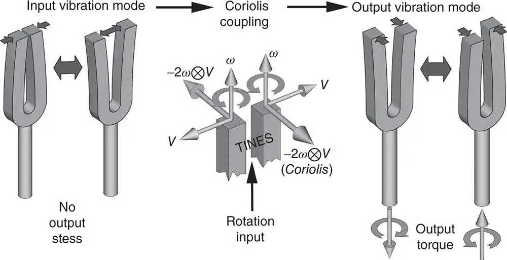
Figure 3.3Tuning fork gyroscope.
MEMS Tuning Fork Gyroscope
A design originally developed at the Charles Stark Draper Laboratories in the 1980s and 1990s [5] does not physically resemble a tuning fork, but it uses the same principle of two masses resonating in the plane of their silicon substrate, and in synchrony to maintain zero net momentum. The input rotation axis is in the plane of the substrate, as illustrated in Figure 3.4. Vibratory motion is controlled by electrostatic “comb drives” (interdigitated electrodes) developed at the University of California at Berkeley. The input axis is in the plane of the substrate and the output vibration mode is normal to the substrate surface. Many improvements have been made in this original design. There are also devices using rotational vibrations coupled with Coriolis effects.
Читать дальшеИнтервал:
Закладка:
Похожие книги на «Global Navigation Satellite Systems, Inertial Navigation, and Integration»
Представляем Вашему вниманию похожие книги на «Global Navigation Satellite Systems, Inertial Navigation, and Integration» списком для выбора. Мы отобрали схожую по названию и смыслу литературу в надежде предоставить читателям больше вариантов отыскать новые, интересные, ещё непрочитанные произведения.


Обсуждение, отзывы о книге «Global Navigation Satellite Systems, Inertial Navigation, and Integration» и просто собственные мнения читателей. Оставьте ваши комментарии, напишите, что Вы думаете о произведении, его смысле или главных героях. Укажите что конкретно понравилось, а что нет, и почему Вы так считаете.