Donald W. McRobbie - Essentials of MRI Safety
Здесь есть возможность читать онлайн «Donald W. McRobbie - Essentials of MRI Safety» — ознакомительный отрывок электронной книги совершенно бесплатно, а после прочтения отрывка купить полную версию. В некоторых случаях можно слушать аудио, скачать через торрент в формате fb2 и присутствует краткое содержание. Жанр: unrecognised, на английском языке. Описание произведения, (предисловие) а так же отзывы посетителей доступны на портале библиотеки ЛибКат.
- Название:Essentials of MRI Safety
- Автор:
- Жанр:
- Год:неизвестен
- ISBN:нет данных
- Рейтинг книги:4 / 5. Голосов: 1
-
Избранное:Добавить в избранное
- Отзывы:
-
Ваша оценка:
Essentials of MRI Safety: краткое содержание, описание и аннотация
Предлагаем к чтению аннотацию, описание, краткое содержание или предисловие (зависит от того, что написал сам автор книги «Essentials of MRI Safety»). Если вы не нашли необходимую информацию о книге — напишите в комментариях, мы постараемся отыскать её.
Reflects the most current research, guidelines, and MRI safety information Explains procedures for scanning pregnant women, managing MRI noise exposure, and handling emergency situations Prepares candidates for the American Board of MR Safety exam and other professional certifications Aligns with MRI safety roles such as MR Medical Director (MRMD), MR Safety Officer (MRSO) and MR Safety Expert (MRSE) Contains numerous illustrations, figures, self-assessment tests, key references, and extensive appendices
is an indispensable text for all radiographers and radiologists, as well as physicists, engineers, and researchers with an interest in MRI.
Essentials of MRI Safety — читать онлайн ознакомительный отрывок
Ниже представлен текст книги, разбитый по страницам. Система сохранения места последней прочитанной страницы, позволяет с удобством читать онлайн бесплатно книгу «Essentials of MRI Safety», без необходимости каждый раз заново искать на чём Вы остановились. Поставьте закладку, и сможете в любой момент перейти на страницу, на которой закончили чтение.
Интервал:
Закладка:
Gradient pulses usually have a trapezoidal waveform ( Figure 1.16). The ability of the gradient system to switch rapidly, known as the slew rate (SR), is defined as the maximum amplitude divided by the rise time required to achieve that amplitude:
(1.4) 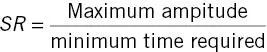
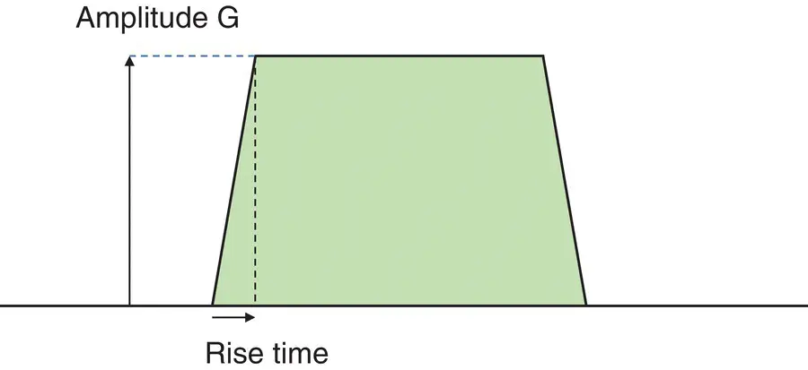
Figure 1.16 Trapezoidal gradient pulse.
Typical slew rates are 100−200 T m −1s −1(tesla per meter per second).
Example 1.2 Gradient performance
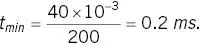
What is the (theoretical) maximum field produced by a 40 mTm −1gradient system with a slew rate of 200 T m −1s −1? What is the minimum rise time?
Assuming that the gradient is linear over a 50 cm FOV, the maximum amplitude at the edge, 25 cm from the iso‐centre is

The minimum rise time is
Radiofrequency subsystem
The radiofrequency system comprises two subsystems: transmit and receive. RF transmit is more important for MR safety.
RF transmission
In most instances a body RF transmit coil is used ( Figure 1.17). This typically has a “birdcage” design, operating in quadrature to produce a circularly‐polarized magnetic field B 1. Some coils may operate in transmit and receive mode (T/R) denoted symbolically as in Figure 1.18. Examples are dedicated T/R head and knee coils. Tx coils usually have a cylindrical geometry, entirely encompassing the anatomical region to produce a uniform B 1so that everything in the FOV experiences the same flip angle.
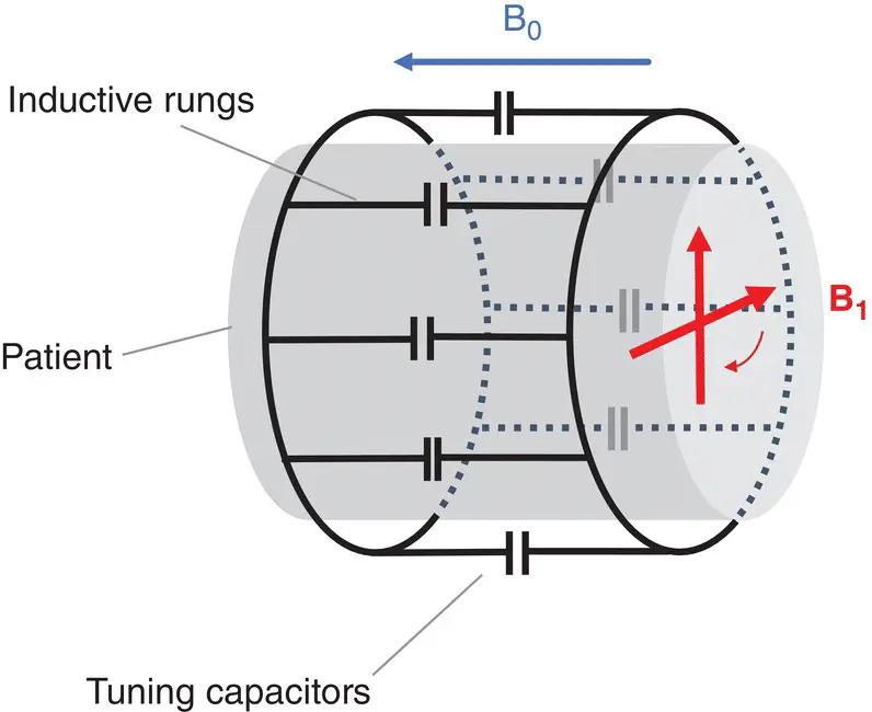
Figure 1.17 Transmit 8‐rung ‘birdcage’ coil to produce a circularly polarised (rotating) B 1+field orthogonal to B 0.
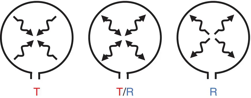
Figure 1.18 IEC 60601‐2‐33 [4] compliant coil labelling: left‐ transmit only; middle‐ transmit‐receive; right‐ receive only.
The coils operate in a resonant mode as tuned circuits, resulting in current amplification to achieve greater B 1at the Larmor frequency. They are driven by powerful RF amplifiers, rated at tens of kilowatts (kW). An important aspect of RF generation is impedance matching, usually to 50 Ω (ohms), to ensure the maximum power transfer from the amplifier to the coil. B 1is of the order of micro‐tesla (μT) peak amplitude.
In 3 T systems, operating at 128 MHz, the B 1‐field in tissue is often quite non‐uniform. In this instance parallel transmit systems can help. These utilize multi‐element Tx coils powered by independent amplifiers capable of changing both the amplitude and phase (relative direction) of the RF pulses ( Figure 1.19).
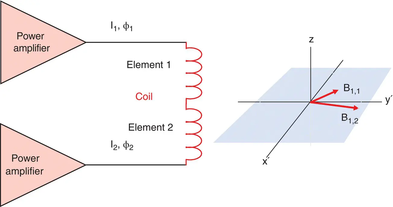
Figure 1.19 Parallel transmit: two (or more) independent RF power amplifiers drive elements of the transmit coil.
RF reception
The purpose of the RF receiver coils is to detect the tiny (micro‐volt) MR signals. A parallel tuned circuit is used ( Figure 1.20) to magnify the voltage prior to pre‐amplification and further processing. The receive coil requires protection circuitry to prevent the large transmit pulses from coupling into the coil. A simple means of achieving this is to use crossed diodes and a detuning capacitor. During the large Tx pulses the diodes conduct and so the total capacitance becomes the sum of both capacitors and the circuit is off‐resonance. During signal detection the diodes do not conduct, and C dis “invisible.” A fault in this circuitry can lead to large induced currents in the coil and potential heating or burns for the patient.
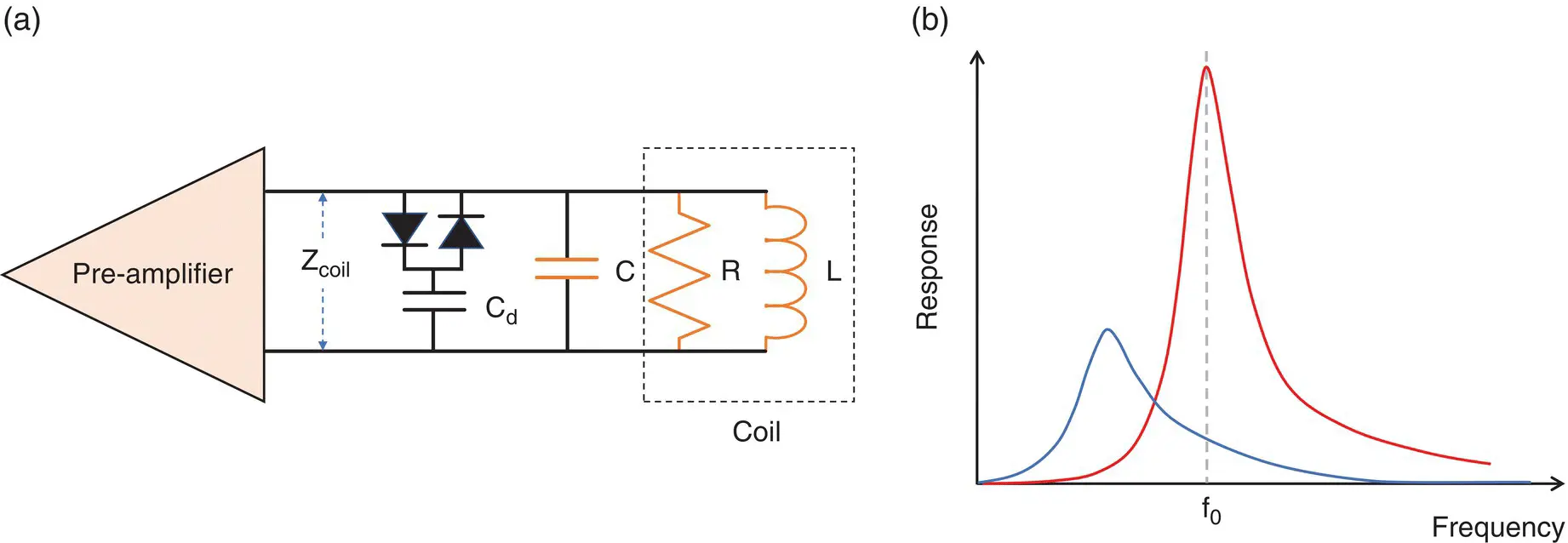
Figure 1.20 Receive coil and pre‐amplifier: (a) the coil has inductance L and resistance R; C dis a detuning capacitor; (b) response of the coil during signal reception (red line) and RF transmission (blue line).
ELECTROMAGNETIC FIELDS
The extent and magnitude of the fields involved in MRI are summarized in table 1.1and Figure 1.21.
Table 1.1 Magnetic fields in MRI.
| Field | Amplitude | Frequency / Slew rate | Pulse duration |
| Static field B 0 | 0.2‐7 T | 0 Hz | Always present |
| Static fringe field spatial gradient dB/dz | 0‐25 T m –1 | 0 Hz | Always present |
| Imaging gradients G x, G y, G z | 0‐80 mT m –1 | 0‐10 kHz 0‐200 T m –1s –1 | 0‐10 ms |
| RF transmit field B 1 | 0‐50 μT | 8‐300 MHz | 0‐10 ms |
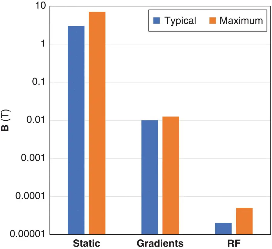
Figure 1.21 Relative magnitude of magnetic fields used in MRI.
Static field
Definition of magnetic flux density and the tesla
Whilst MR practitioners commonly refer to their magnets in terms of “magnetic field strength”, this nomenclature is scientifically incorrect. The proper term is magnetic flux density , denoted as B. Bis a vector field with components in each direction B x, B yand B z. MRI is only sensitive to B zand that is what we refer to colloquially as the “field.” Magnetic flux density has the SI (International System) unit of the tesla (T). An older unit is the gauss (G). One tesla equals 10 000 G.
The scientific definition of the tesla is in terms of force. Referring to Figure 1.22, one tesla is the amount of magnetic flux density which exerts a force of one newton (N) on a charged particle of charge one coulomb (C) moving at right angles to the field direction with a velocity of one meter per second (m s −1). It’s not an easy definition, but the fact that it is defined in terms of force is highly apt for MR safety!
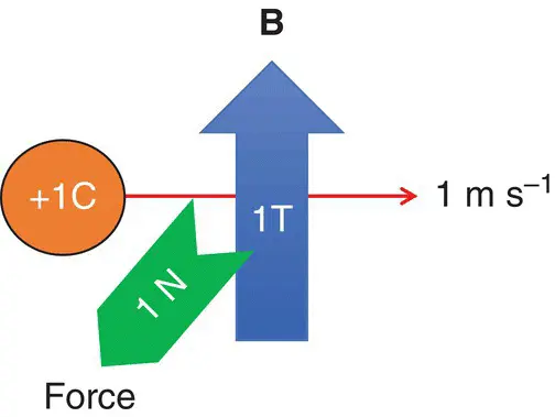
Figure 1.22 Definition of the SI unit tesla.
MYTHBUSTER:
The unit of “magnetic field strength” is not the tesla, but is amperes per meter. B is the magnetic flux density .
Читать дальшеИнтервал:
Закладка:
Похожие книги на «Essentials of MRI Safety»
Представляем Вашему вниманию похожие книги на «Essentials of MRI Safety» списком для выбора. Мы отобрали схожую по названию и смыслу литературу в надежде предоставить читателям больше вариантов отыскать новые, интересные, ещё непрочитанные произведения.


Обсуждение, отзывы о книге «Essentials of MRI Safety» и просто собственные мнения читателей. Оставьте ваши комментарии, напишите, что Вы думаете о произведении, его смысле или главных героях. Укажите что конкретно понравилось, а что нет, и почему Вы так считаете.