Donald W. McRobbie - Essentials of MRI Safety
Здесь есть возможность читать онлайн «Donald W. McRobbie - Essentials of MRI Safety» — ознакомительный отрывок электронной книги совершенно бесплатно, а после прочтения отрывка купить полную версию. В некоторых случаях можно слушать аудио, скачать через торрент в формате fb2 и присутствует краткое содержание. Жанр: unrecognised, на английском языке. Описание произведения, (предисловие) а так же отзывы посетителей доступны на портале библиотеки ЛибКат.
- Название:Essentials of MRI Safety
- Автор:
- Жанр:
- Год:неизвестен
- ISBN:нет данных
- Рейтинг книги:4 / 5. Голосов: 1
-
Избранное:Добавить в избранное
- Отзывы:
-
Ваша оценка:
Essentials of MRI Safety: краткое содержание, описание и аннотация
Предлагаем к чтению аннотацию, описание, краткое содержание или предисловие (зависит от того, что написал сам автор книги «Essentials of MRI Safety»). Если вы не нашли необходимую информацию о книге — напишите в комментариях, мы постараемся отыскать её.
Reflects the most current research, guidelines, and MRI safety information Explains procedures for scanning pregnant women, managing MRI noise exposure, and handling emergency situations Prepares candidates for the American Board of MR Safety exam and other professional certifications Aligns with MRI safety roles such as MR Medical Director (MRMD), MR Safety Officer (MRSO) and MR Safety Expert (MRSE) Contains numerous illustrations, figures, self-assessment tests, key references, and extensive appendices
is an indispensable text for all radiographers and radiologists, as well as physicists, engineers, and researchers with an interest in MRI.
Essentials of MRI Safety — читать онлайн ознакомительный отрывок
Ниже представлен текст книги, разбитый по страницам. Система сохранения места последней прочитанной страницы, позволяет с удобством читать онлайн бесплатно книгу «Essentials of MRI Safety», без необходимости каждый раз заново искать на чём Вы остановились. Поставьте закладку, и сможете в любой момент перейти на страницу, на которой закончили чтение.
Интервал:
Закладка:
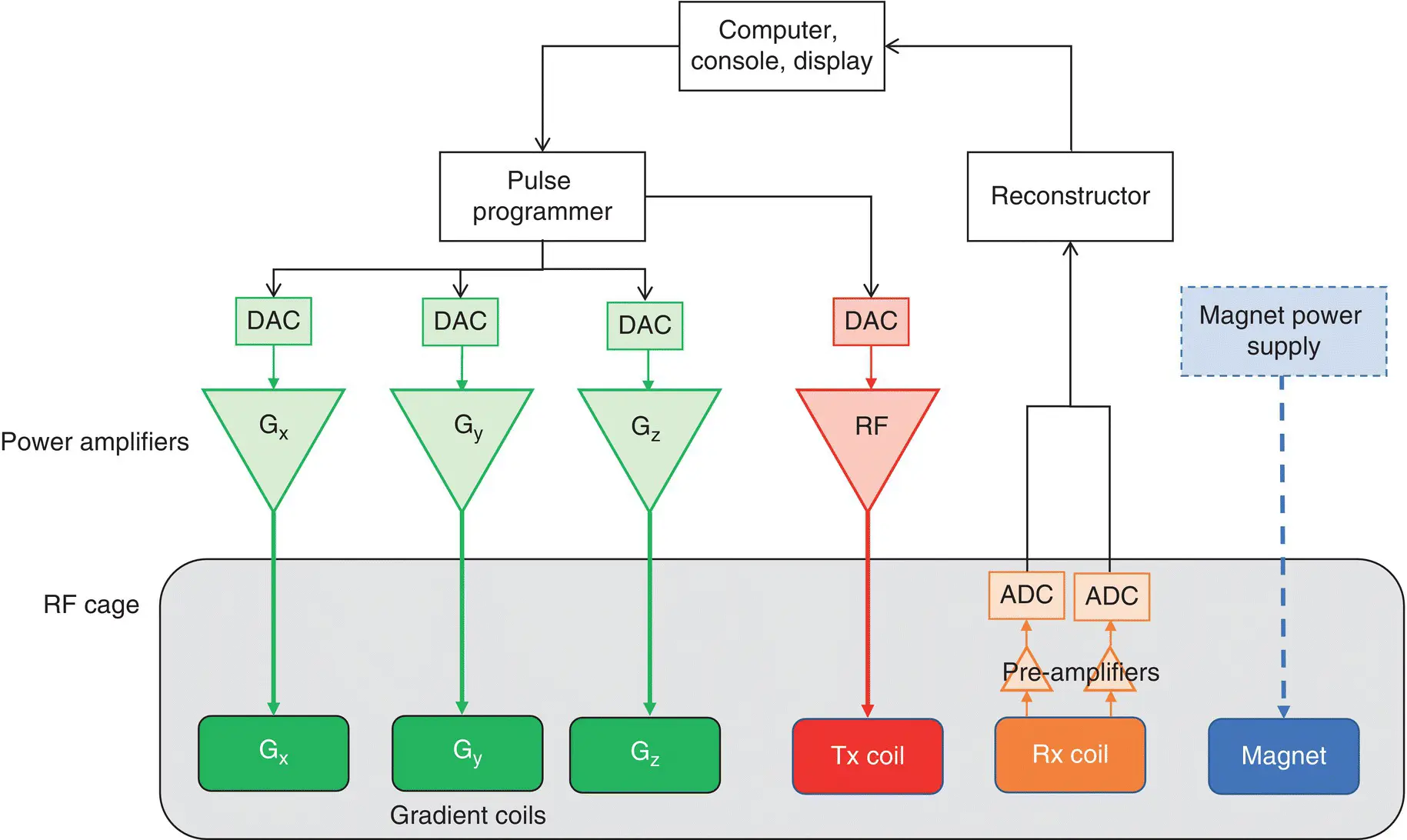
Figure 1.12 Schematic of principal MRI system components: DAC is digital‐to‐analog convertor; ADC is analog‐to‐digital convertor; Tx transmit; Rx receive; black lines denote digital signal; colored lines denote analogue signal. The magnet power supply is only required for the initial ramp‐up.
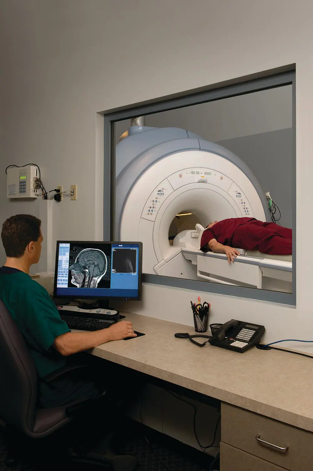
Figure 1.13 MRI operator’s console in the control room with observation window into the magnet room. Source: James Steidl/iStockphoto.
Magnet system
The magnet is the largest single component of the system. Most systems use superconducting magnets. Superconductivity is a quantum mechanical property whereby, below a critical temperature T c, an electrical conductor loses its electrical resistance, enabling large electrical currents to be sustained in perpetuity without a driving voltage from a power supply. As long as the windings are kept sufficiently cold, the current and hence the magnet’s field persists indefinitely. Liquid helium with a boiling point of −269 °C (4.3 K or kelvin) is used for cooling. Safety consequences of this are considered in Chapter 12.
Superconductivity
Superconductivity was discovered by Dutch scientist Heike Kamerlingh Onnes in 1911, but it took until 1957 for Bardeen, Cooper, and Schrieffer to formulate a quantum mechanical theory (BCS theory) to account for the phenomenon. The electrical resistance of a non‐superconducting metal, such as copper, depends upon its temperature, decreasing with lower temperatures, but possessing a finite resistance even at absolute zero (−273.15 °C). Below T cthe electrons in a superconductor pair up into “Cooper pairs” acting as a superfluid resulting in zero resistance (FIGURE 1.14a).
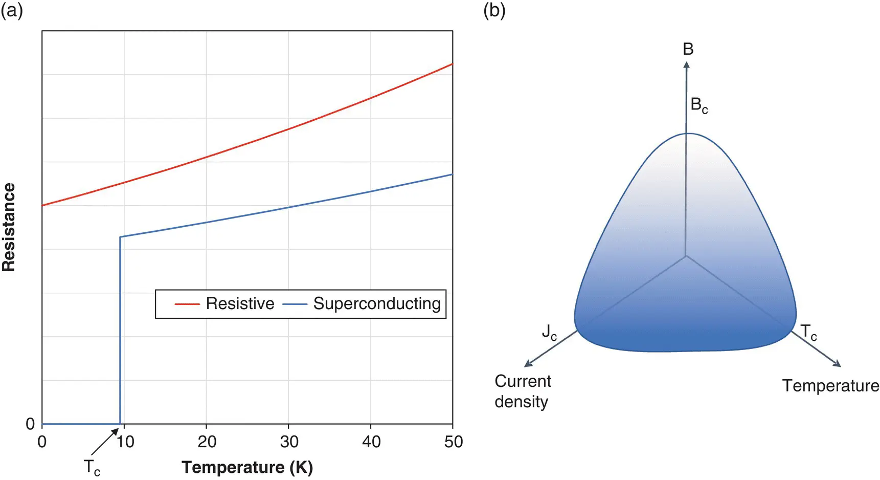
Figure 1.14 Superconductivity: (a) resistance v temperature for a superconductor and a non‐superconductor; (b) Superconducting phase diagram: each of temperature, current density and magnetic field must be below a critical value T c, J c, B cto maintain the superconductive state.
Niobium titanium (Nb‐Ti) alloy used in MR magnets is a type 2 superconductor. 1 It has a second, higher critical temperature at which some magnetic flux may exist within the material. Superconductivity behaves as a thermodynamic phase with a relationship between temperature, field, and current density ( Figure 1.14b). There is a critical field B cand current density J cabove which the superconductive state cannot exist. This puts an ultimate limit on the field strength that can be achieved. Nb‐Ti has a T cof 9.5 K and B cof 15 T. Niobium‐tin (Nb‐Sn) alloy can sustain higher fields.
High temperature superconductors can have T cabove 90K and can be cooled using liquid nitrogen (N) with a boiling point of 77 K (−196 °C) or with cooled helium gas. These have been used to produce 0.5 T MRI magnets, but not operating in a persistent current mode. Research is ongoing with the prospect of simplifying the cooling system and reduced dependence upon helium. Helium is a by‐product of natural gas extraction, a limited resource. Nitrogen can be produced from the atmosphere.
Superconducting MR magnets
Superconducting magnets are capable of generating magnetic flux densities, colloquially referred to as “magnetic field strength”, up to 7 T (tesla) in currently available systems. 1.5 and 3 T systems are most common. B 0is orientated horizontally along the scanner bore or patient aperture, by convention denoted as the z‐axis.
Figure 1.15shows a schematic of a modern MRI magnet in cross‐section. There are two sets of windings: the field coils and the shield coils. The shield coils are wound in opposition to the field coils in order to reduce the extent of the fringe field . The windings are held in a large vessel or cryostat and bathed in liquid helium. Surrounding this is a vacuum to prevent conduction and convection heating, and layers of highly reflective sheeting to prevent radiative heating.
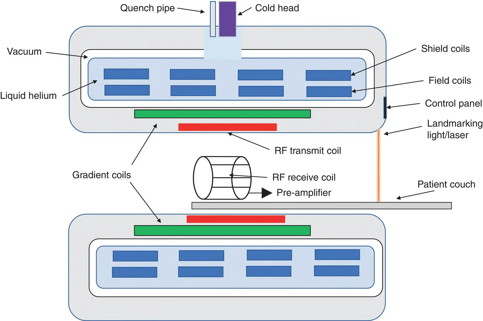
Figure 1.15 Schematic of a self‐shielded superconducting MRI system.
During operation some helium will evaporate or “boil off”. In older magnets this was wasted as exhaust, but modern magnets have a refrigeration system, the cold head or cryo‐cooler which re‐condenses the gas as liquid. Such “zero boil‐off” systems generally do not require helium replenishment. If electrical power is lost, the reliquification will not occur, but the magnet can stay cold for several days. This allows new systems to be transported cold.
To generate the field initially, a power supply is required. The process of energizing the magnet or “ramping up” involves a gradual increase of electrical current. A superconducting switch or shunt is maintained in a non‐superconductive state by a small heater whilst the current grows. At the desired current the heater is turned off and the switch becomes superconducting, completing the electrical circuit. The power supply can then be disconnected and removed from site. The reverse process, ramping down, can be used to reduce or remove the field when required, e.g. for a major hardware upgrade or after a non‐injurious ferromagnetic incident to remove the offending object.
The Nb‐Ti wires are 50–150 μm in diameter, embedded in a copper matrix. This provides additional mechanical strength – they are subject to significant magnetic forces – and provides a means for conducting excess heat and current in the event of a magnet failure or quench to prevent damage to the more delicate Nb‐Ti filaments. In the superconducting state, the copper matrix acts like an insulator, providing isolation between the Nb‐Ti strands.
Short larger‐bore magnets
A recent industry trend has been to reduce the length of the magnet, typical to around 1.6 m and to increase the diameter of the bore from 60 to 70 cm to afford better patient comfort and to accommodate larger patients. This has implications for safety as it affects the fringe field (see Fringe field spatial gradient, page 19).
Other magnets
Other configurations of MRI systems are also available, although less common. Resistive magnets producing fields up to 0.4 T are sometimes configured as open or C‐arm systems, affording better access to the patient and a less claustrophobic experience. Resistive magnets have one safety‐related advantage: the field can be routinely switched off.
Permanent magnets are used in low field niche scanners for extremity imaging or in “upright systems”. These employ various rare earth materials such as neodymium‐iron‐boron (Nd‐Fe‐B). Their magnetic field is always present.
Imaging gradients subsystem
Magnetic field gradients G x, G y, and G zused to spatially select or encode the MR signal during acquisition are generated by three sets of gradient coils. The field generated is always along z. Gradient coils usually require water cooling as they have typically hundreds of amperes (A) of electricity pulsed through them. Specialist hybrid amplifiers and power supplies are used to generate these strong pulses. A consequence of gradient pulsing is the generation of acoustic noise ( Chapter 7).
Читать дальшеИнтервал:
Закладка:
Похожие книги на «Essentials of MRI Safety»
Представляем Вашему вниманию похожие книги на «Essentials of MRI Safety» списком для выбора. Мы отобрали схожую по названию и смыслу литературу в надежде предоставить читателям больше вариантов отыскать новые, интересные, ещё непрочитанные произведения.


Обсуждение, отзывы о книге «Essentials of MRI Safety» и просто собственные мнения читателей. Оставьте ваши комментарии, напишите, что Вы думаете о произведении, его смысле или главных героях. Укажите что конкретно понравилось, а что нет, и почему Вы так считаете.