The localization of the MR signal within a slice is usually achieved by two processes: phase‐encoding (PE) and frequency‐encoding (FE), each using gradient pulses along orthogonal directions. These pulses encode the MR signal in terms of spatial frequencies. Image acquisition requires multiple repetitions of the basic block of a pulse sequence using a different amplitude of PE pulse each time ( Figure 1.7). TR is the time interval between successive repetitions. Image reconstruction is achieved by the mathematical operation of a two‐dimensional (2D) Fourier transform.
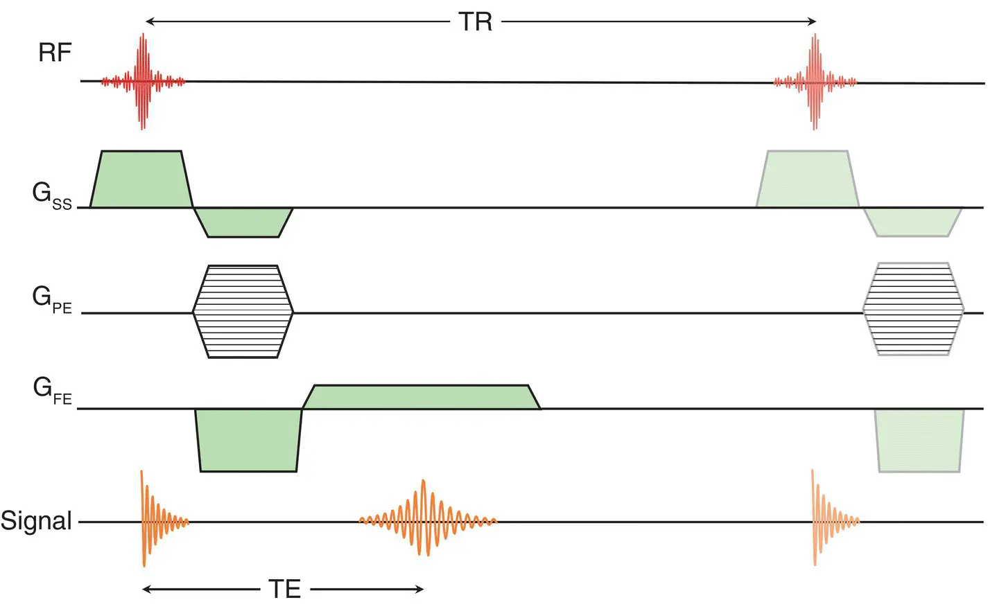
Figure 1.7 Simple 2D pulse gradient echo (GRE) sequence showing pulse amplitudes and timings of the components.
The application of a second set of PE gradients in conjunction with the selection of a thicker slab of tissue makes three‐dimensional (3D) imaging possible ( Figure 1.8).
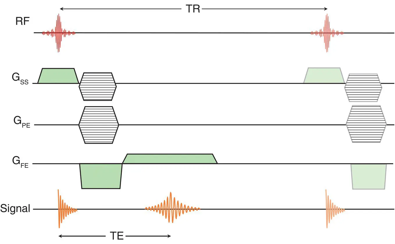
Figure 1.8 3D imaging sequence with a second phase‐encode gradient in the slab direction.
A clinical scanner has many different pulse sequences available, broadly designated as either gradient echo (GRE) or spin echo (SE). In GRE (e.g. Figure 1.7) each signal collected arises from a low flip angle RF pulse, typically less than 40°. T 1‐weighted images are generated using so‐called spoiled gradient echo. Rewound GRE uses slightly higher flip angles (>40°), producing bright‐fluid images, popular in cardiac MRI. GRE images are shown in Figure 1.9.
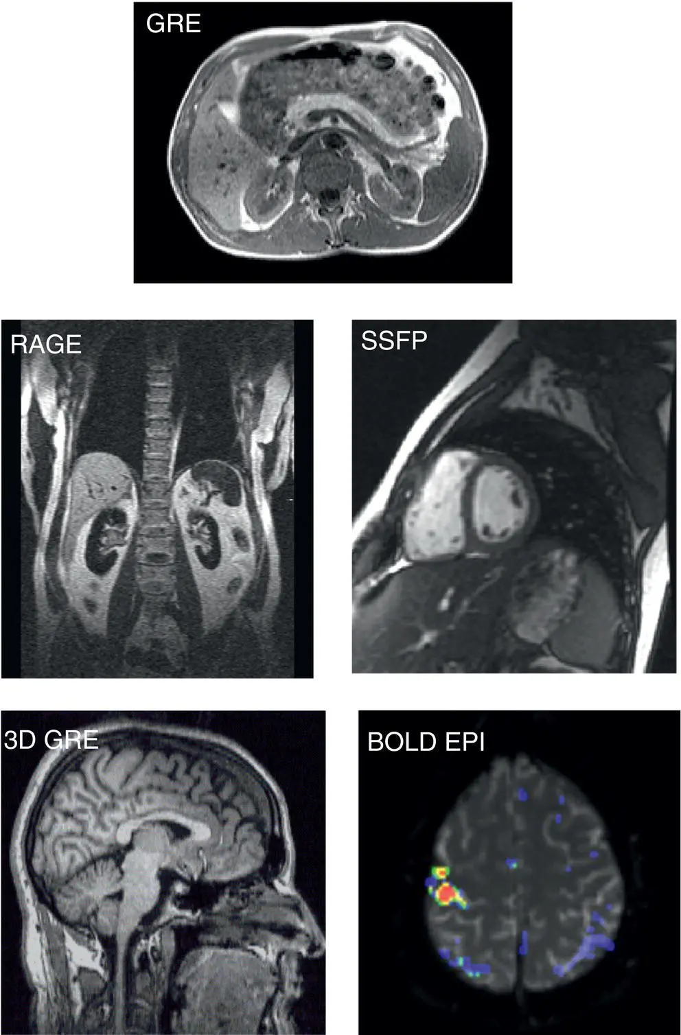
Figure 1.9 Gradient echo images: Gradient echo (GRE) abdomen; Rapid Acquired Gradient Echo (RAGE); 3‐D Gradient Echo (3D GRE); Steady State Free Precession (SSFP) heart; BOLD‐EPI with brain activation map overlay. Source: Flinders Medical Centre, Adelaide, Australia; Charing Cross Hospital, London, UK. Reproduced with permission.
The SE sequence was initially developed for its ability to recover signal loss arising from B 0inhomogeneities. These occur across the field‐of‐view (FOV) as dephasing, or “fanning out”, of transverse components of the magnetization ( Figure 1.10) following a 90° pulse. By applying a 180° pulse orthogonal to the 90° pulse (and also to B 0), the fan of magnetization vectors is twisted around in such a way that those with a phase lag advance in phase and vice‐versa. At time TE, equal to twice the interval between the 90° and 180° pulses, the magnetization rephases, giving a strong echo whose magnitude depends upon the tissue T 2.
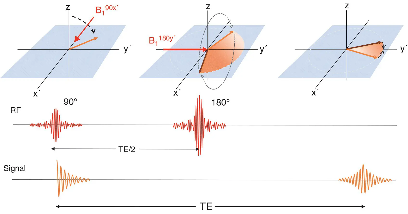
Figure 1.10 Spin echo formation: following a 90° pulse aligned with the x’ axis, magnetization in the x’y’ plane dephases; a 180° pulse aligned with the y‘‐axis inverts the phase of the magnetization to form a spin echo at time TE. The prime (‘) indicates a frame of reference rotating at the Larmor frequency.
Spin echo can be further enhanced by using multiple 180° pulses to form a series or train of echoes, each of which can have different phase‐encoding applied. In Turbo or Fast Spin Echo (TSE/FSE) the overall scan time is reduced by the echo train length (ETL) or Turbo‐factor (TF). Typical ETL/TFs are in the range 3–20, although single shot acquisitions with 128–256 echoes are also possible.
The addition of a preparation 180° pulse prior to the 90° inverts the magnetization to lie along the ‐z axis. As each tissue recovers towards +M 0, there is a time at which its magnetization passes through zero. An image formed at this point, will not contain signal from that tissue. Short TI Inversion Recovery (STIR) removes fat from the image, whilst FLuid Attenuated Inversion Recovery (FLAIR) removes the cerebrospinal fluid (CSF). Typical SE images are shown in Figure 1.11.
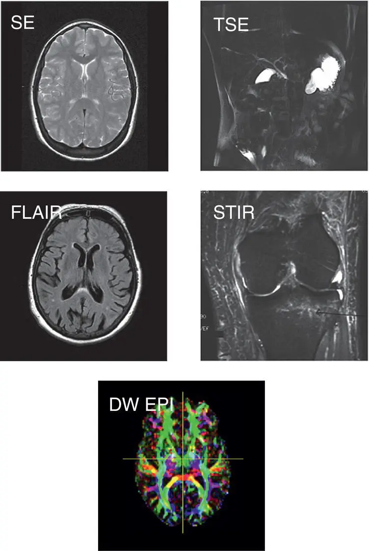
Figure 1.11 Spin echo images: (a) Spin echo (SE) T 2‐weighted brain; single shot Turbo (fast) Spin Echo (TSE) MR cholangio‐pancreatogram; Fluid Attenuated Inversion Recovery (FLAIR) brain; Short TI Inversion Recovery (STIR) knee; Diffusion EPI (Echo Planar Imaging) showing white matter directional anatomy. Source: Flinders Medical Centre, Adelaide, Australia. Reproduced with permission.
In parallel imaging a multi‐element RF receive array coil is used to provide additional spatial information, and to reduce the number of lines of signal required to form an image. Parallel imaging reduces the number of TR periods of an acquisition by an amount known as the reduction factor R, SENSE factor or iPAT factor. The use of parallel imaging reduces the patient’s overall RF exposure.
Overview of MRI applications
Since its adoption in the late 1980s the scope of MRI’s clinical applications has grown, and continues to grow. Brain, spine, and musculoskeletal imaging were the first major applications.
MRI’s ability to differentiate between grey and white matter in the brain led to its deployment in neuroradiology, particularly for white matter disease and brain tumors. The development of diffusion‐weighted imaging (DWI) gives MRI the ability to detect acute stroke and chronic infarct. Functional MRI (fMRI) is a popular tool in neuroscience research which utilizes the Blood Oxygenation Level Dependent (BOLD) effect to map neural activation. White matter connectivity can be investigated using diffusion tensor imaging (DTI) or high angular diffusion imaging (HARDI) and tractography. In musculoskeletal MRI soft tissue components, muscle, bone marrow, fat, and cartilage are all visible. Whilst tendon, ligament, and cortical bone are inferred by their absence of signal, edema resulting from injury is highly conspicuous.
MRI has a major role in oncology through tumor imaging, often using DWI for diagnosis, staging, and treatment assessment. Applications include breast, bowel, prostate, liver, pancreas, female pelvis, in addition to brain and spine. MR spectroscopy (MRS) provides in‐vivo bio‐chemical information on tumor and tissue metabolism. Through sensitizing the MR signal to flow or by the injection of a gadolinium‐based contrast agent (GBCA) angiographic images can be obtained to investigate vascular disease. The development of rapid GRE sequences has facilitated cardiac MR for heart morphology and function studies. GRE using the in‐phase–out‐of‐phase technique is applied in liver and abdominal imaging of adenoma and cirrhosis, whilst TSE/FSE can indicate cysts, hepatocellular carcinoma and metastases. Single‐shot TSE/FSE is used for MR cholangio–pancreatography (MRCP) in the biliary system. Some of these are illustrated in Figures 1.8and 1.10.
The heart of the MRI system is the magnet, creating the static B 0field that produces the tissue magnetization. The B 1pulse that manipulates the magnetization is generated by a RF transmit coil (Tx) or coils fed by high‐powered broadband RF amplifiers. The pulse shapes are generated digitally and converted to analog waveforms prior to amplification. The gradient coils provide the pulses used for spatial encoding of the signal. Finally, the MR signal is detected by receiver coils (Rx). These are usually positioned close to the anatomy of interest to maximize the signal received. Most receive coils are array or matrix coils formed from numerous minimally interacting smaller elements . The advantages of array coil technology include improved signal‐to‐noise ratio (SNR) and the ability to utilize parallel imaging techniques. Once detected, the MR signal is demodulated, i.e. the RF “carrier” component (at f 0) is removed, as the spatial information is stored in the VLF signal region. With “direct digital” systems, demodulation and digitization are applied directly to the amplified RF signal, close to or at the coil. The ensuing signals are transmitted digitally or optically and stored for reconstruction. Figure 1.12shows a schematic of a typical MR system. The gradient and RF amplifier systems, control and signal processing systems, and cooling equipment are situated in the equipment or technical room, external to the MR examination or magnet room. The console and host computer are located in the control room ( Figure 1.13).
Читать дальше
