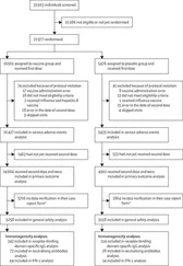
Nowhere is this better illustrated than in the tragic case of a six‐year old boy who in 2001 was struck by an oxygen tank which had flown into the scanner, later dying from his injuries. This prompted a root and branches review of MR safety practice within the USA by the American College of Radiology [2] leading to a series of recommendations. It is concerning, that even today, not all these recommendations are routinely followed in every institution. In a 10‐year review of MRI‐related incidents reported to the US Food and Drug Authority (FDA) 59% were thermal (excessive heating, burns), 11% mechanical (cuts, fractures, slips, falls, crush and lifting injuries), 9% from projectiles, and 6% acoustic (hearing loss) [3] ( Figure 1.2).

Figure 1.2 MRI adverse events reported to the FDA. Data from [3].
A significant source of risk from MRI arises when patients have implants, particularly active implanted medical devices (AIMDs), such as cardiac pacemakers or neuro‐stimulators. However, whereas a decade ago, custom might have been pre‐cautionary – not to scan these patients, modern practice is moving towards finding ways to scan whenever there may be significant benefit to the patient. This requires that all MR practitioners have a deeper understanding of the possible interactions between the device, human tissues, and the scanner, and of MR safety in general. That is the purpose of this book, to ensure all MR practitioners have sufficient knowledge to practise safely for the benefit of their patients.
OVERVIEW OF MRI OPERATION
MRI relies upon the properties of nuclear magnetism. The nucleus of an atom consists of subatomic particles: electrically neutral neutrons and positively charged protons. In an atom the electrical charge of the protons is usually balanced by the negative charge of the surrounding electron cloud. MRI concerns the nucleus of hydrogen, mainly as it occurs in water and fat molecules.
Nuclear magnetic resonance
Hydrogen is the simplest element in the universe with the atomic number of one, meaning its nucleus possesses a single proton. The proton is said to exhibit a property known as spin . The consequences of spin only become observable in an externally applied magnetic field (denoted B 0) in which the proton spins precess , like spinning tops or gyroscopes, around the direction of B 0. In the external field the proton spins must adhere to specific energy levels or quantum basis states ( Figure 1.3a). A slight imbalance between the populations of these results in a net magnetization, M 0( Figure 1.3b). M 0can be manipulated by applying the appropriate frequency (or energy) of electromagnetic radiation. This is the Larmor or resonance frequency :
(1.1) 
where the subscript “0” means “at resonance”. γ (“gamma bar”) is the gyromagnetic ratio of the hydrogen nucleus. When frequency f is expressed in MHz and B 0in tesla, γ has a value of approximately 42.58 MHz T ‐1. This simple relationship underpins all of MRI.
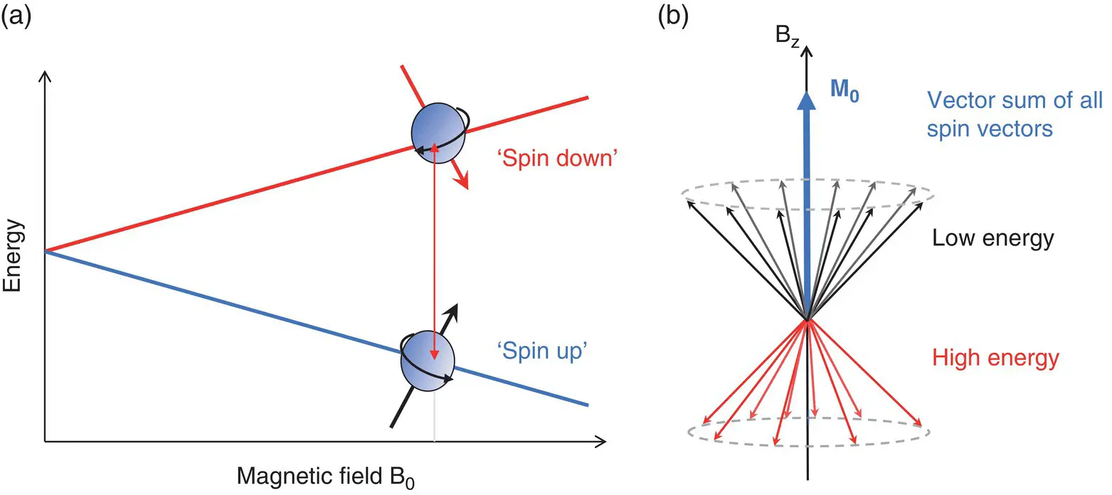
Figure 1.3 Nuclear magnetism: (a) basis state energy differences; (b) formation of macroscopic magnetization M 0from the sum of basis state spin vectors.
The radiofrequency energy is applied as a magnetic field B 1orthogonal to the direction of B 0( Figure 1.4). Whilst B 1is present the magnetization precesses around both B 0and B 1directions, tipping away from the z‐axis (usually head–foot) of the scanner. B 1is applied in a short burst as a RF pulse. The angle of deflection away from the z‐axis is known as the flip angle α. For a simple rectangular shaped RF pulse this is
(1.2) 
where t pis the duration of the pulse (in seconds), B 1is the amplitude of the “excitation” pulse (in tesla), and γ = 2π × γ (2.68 × 10 8radians s ‐1).
What B 1amplitude is required for a 1 ms rectangular shaped RF pulse to produce a flip angle of 90°?
Express α in radians (=  ). From Equation 1.2


Figure 1.4 Excitation of the macroscopic magnetization Mby the B 1RF field.
Once excited, the magnetization recovers towards its initial equilibrium value M 0by two independent relaxation processes: T 1 relaxation restores the longitudinal or z‐component of magnetization towards M 0; T 2 relaxation causes the transverse component, the signal , to decay to zero. T 1and T 2 relaxation times vary by tissue type and exhibit changes due to pathology, often increasing where disease or injury is present.
Image formation is achieved by varying the value of magnetic field in the z‐ or B 0direction. The field variation is applied by passing electrical pulses through one or more sets of gradient coils , forming the gradient pulses. The gradients, known as G x, G y, G z, are designed to produce linear variations in the z‐component of the magnetic field with respect to the x, y, and z axes ( Figure 1.5). In terms of their function in image formation they are known as slice‐select (G SS), phase‐encode (G PE), or frequency‐encode (G FE).
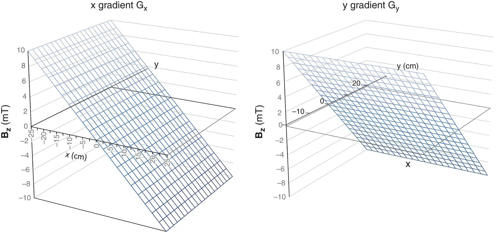
Figure 1.5 B zfrom magnetic field gradients G xand G y.
By applying a narrow bandwidth B 1pulse, shaped to include a limited range of frequencies, simultaneously with the slice select gradient G ss, the excitation region is restricted to a narrow slice of the patient’s anatomy with a width or thickness:
(1.3) 
The slice thickness can be controlled by changing the amplitude of the slice‐select gradient or by changing the bandwidth of the RF pulse. The slice orientation can be selected by using different gradient coils (or a combination of coils for oblique views). By changing the RF frequency images may be acquired as a series of 2D multiple slices at different locations ( Figure 1.6).
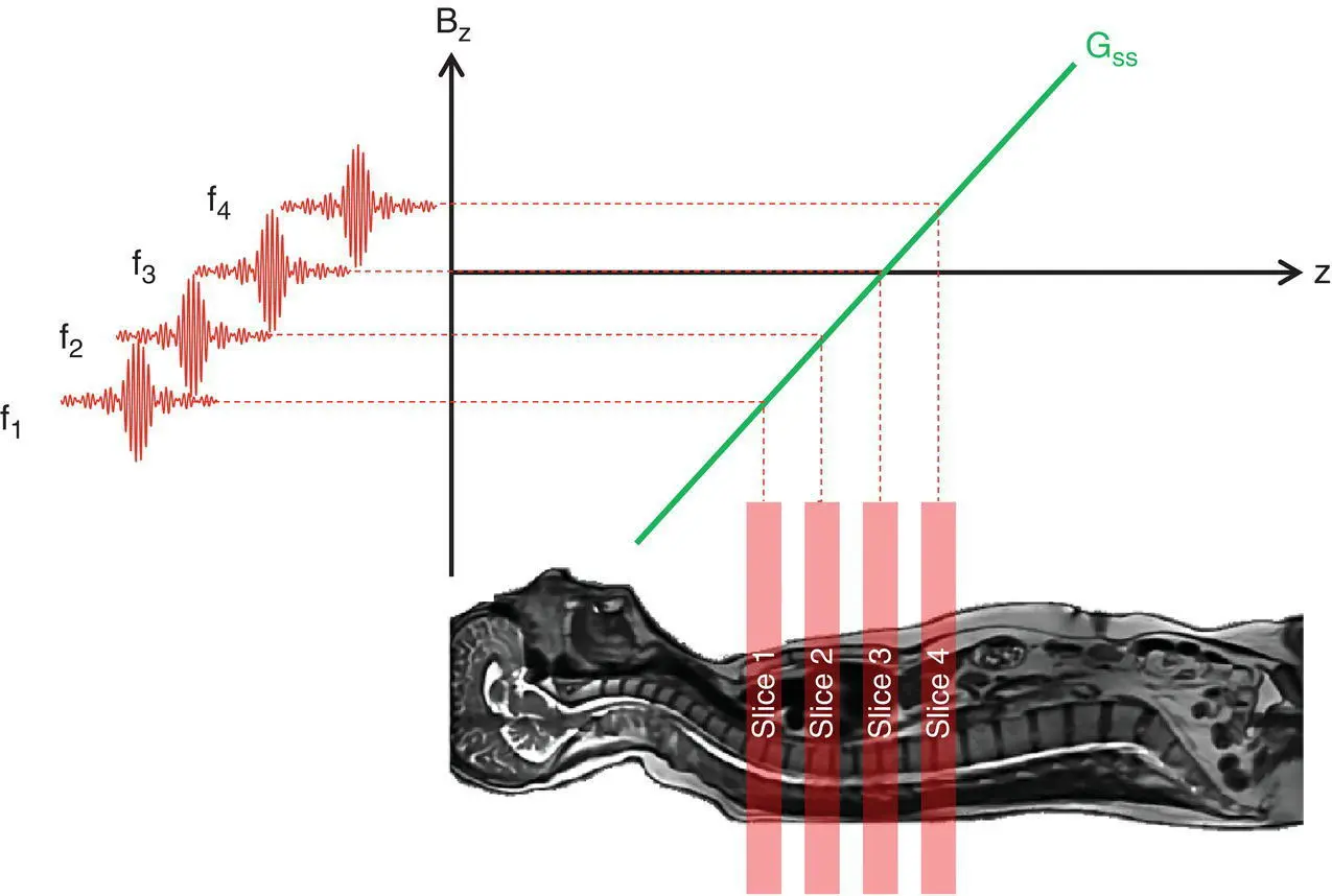
Figure 1.6 Multiple slice imaging. Changing the frequency of each RF pulse whilst a gradient G ssis applied selects a different slice position.
Читать дальше


 ). From Equation 1.2


