5 5. Lui, Y., Shen, J., Kainz, W. et al. (2013). Numerical investigations of MRI RF field induced heating for external fixation devices. BioMedical Engineering OnLine 12:12 doi.org/10.1186/1475‐925X‐12‐12.
6 6. ASTM F2503‐13 (2015). Standard Practice for Marking Medical Devices and Other Items for Safety in the Magnetic Resonance Environment. West Conshohocken, PA: ASTM International.
Further reading and resources
1 McRobbie, D.W., Moore, E.A., Graves, M.J., et al. (2017). MRI from Picture to Proton 3rd edn. Chapters 3, 4, 8, 9, and 10. Cambridge, UK: Cambridge University Press.
1 1In type 1 superconductors the magnetic field inside the material is zero due to the Meissner Effect.
2 2This is not true in tissue. See Chapter 2, page 54.
3 3Using complex notation where, the operator eiωt signifies circular motion.
2 Let’s get physical: fields and forces
BASIC LAWS OF MAGNETISM
The fundamental laws of magnetism were summarized by Scottish physicist James Clerk Maxwell in four equations. These equations are not for the faint‐hearted nor for the mathematically challenged, but if you aspire to be an expert in MRI safety, then you should have a good understanding of their consequences. By comparison, if you did not understand Newton’s laws of gravitation or Einstein’s theory of relativity you would not become a rocket scientist. Maxwell’s equations underpin everything in electromagnetism: the biological effects of EM fields, interactions with implants, electromagnetic modeling of field exposures and specific absorption rate (SAR), projectiles and magnet safety, magnetic shielding, fringe field gradients, and acoustic noise. A full understanding requires some knowledge of vector calculus and differential equations (see Appendix 2) but for now we will not need this. Those aspiring to be MR Safety Experts should read this chapter in conjunction with Appendix 1.
Understanding Maxwell’s Equations
Maxwell’s equations are given in Appendix 1. Here we describe their main consequences for MRI safety.
Electrical charge and electric fields
Gauss’s Law (Maxwell’s first equation) describes how electrical charges produce static electric fields E. Electric fields start at a positive charge and are directed towards their conclusion at negative charges ( Figure 2.1). We are not going to use Gauss’s Law much, although it has relevance in minimizing unwanted electric fields in coil design, and at some tissue boundaries where charge may accumulate.
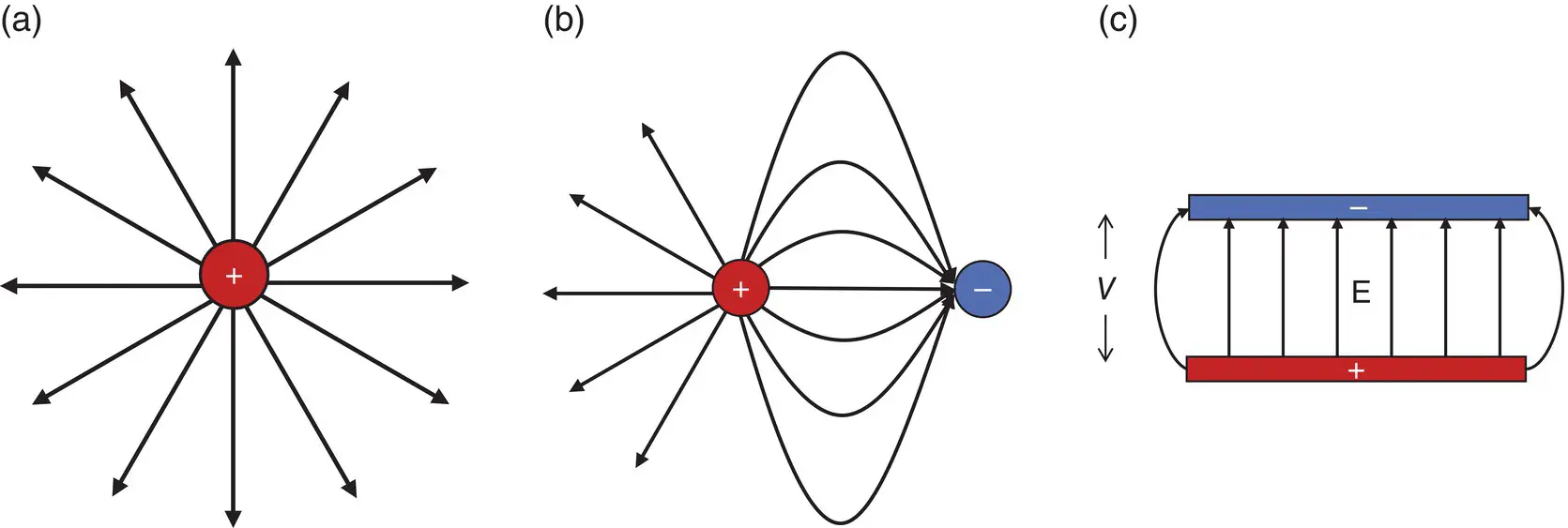
Figure 2.1 Electric field lines begin at a source of positive charge and terminate at a negative charge: (a) single point positive charge; (b) positive and negative point charges; (c) capacitor with a potential difference V between the plates.
Maxwell’s second equation states that the “divergence of B is zero.” This means that there is no magnetic equivalent of electrical charge – no “magnetic monopoles”. Magnetic sources are not like electrostatic ones, but exist as dipoles with a north and south pole (just like the Earth). Magnetic field lines have no beginning or end, but form complete loops from north pole to south ( Figures 2.2, 1.23). The nature of the B 0fringe field depends upon this.
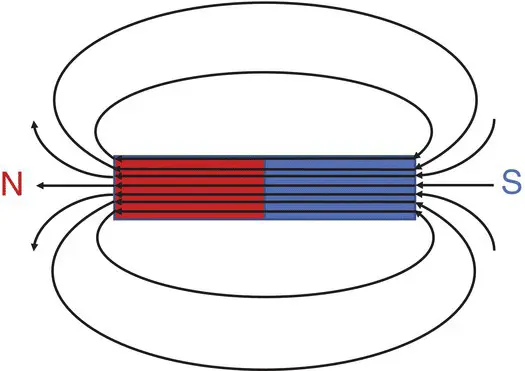
Figure 2.2 Magnetic field lines from a permanent bar magnet.
Electromagnetic induction
Maxwell’s third equation is also known as Faraday’s Law of Induction. We have met dB/dt already in Chapter 1, so clearly this equation is going to have significant implications for us. It states that a time‐varying magnetic field induces an electric field; also, that the electric field lines form complete loops unlike static electric fields ( Figure 2.3). The induced electric field is sometimes called “conservative” as it involves no external static charges. Faraday’s Law is also responsible for the detection of the MR signal in an RF receive coil – so it’s important!
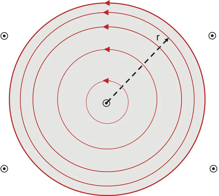
Figure 2.3 Electric fields induced by a time‐varying magnetic field form complete loops (unless there are static electrical charges present); dB/dt is into the page.
Maxwell’s fourth equation, or Ampere’s Law, tells us that magnetic fields can be generated both by electric currents and by time‐varying electric fields, allowing for the existence of electro‐magnetic waves – everything in the electromagnetic spectrum: gamma rays, X‐rays, ultraviolet, visible light, infrared, microwaves, and radiowaves ( Figure 2.4). It has consequences for the more “wave‐like” behavior of the B 1excitation field at higher frequencies. It also results in field exposures from the gradients being higher than intuitively anticipated.
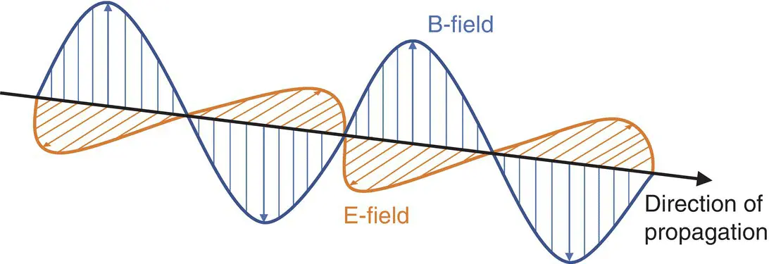
Figure 2.4 Electromagnetic wave: the magnetic and electric fields are orthogonal to each other and to the direction of propagation.
Generating magnetic fields
Maxwell’s equations teach us that a magnetic field (we shall drop the proper term “flux density”) is generated by an electrical current. In this section we consider the generation of magnetic fields from conductors and coils in various simple configurations. Further detail is given in Appendix 1.
B field from a long straight conductor
If we have a straight wire and pass a current I along it, then the magnetic field generated will have circular field lines ( Figure 2.5). The direction of the field lines can be determined by the “right hand rule”, namely that if your right hand’s thumb represents the direction of current flow, then your cupped fingers will indicate the circular B field direction, denoted B θ. The magnitude of the field at a radial distance r from the wire is proportional to 1/r. The subscript θ (from polar coordinates‐ see Appendix 2) indicates that the field lines form circular paths around the wire.
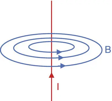
Figure 2.5 Magnetic field lines from a long straight conductor carrying current I. The direction of the lines follows the right‐hand rule.
B field from loop conductors
The field on the z‐axis from a circular loop of radius a is directed along the z‐direction and is proportional to the current I. At the centre of the loop B is proportional to 1/a, so the field generated depends upon the radius of the coil. At long distances from the loop, it acts like a magnetic dipole . On‐axis the field only has a B zcomponent with a 1/z 3dependence. This is often cited to represent the dropping off of the B 0fringe field, but modern shielded MRI magnets do not exactly follow this behavior; they are not simple dipoles. Nevertheless, the 1/z 3dependence serves as a useful approximation of the nature of the fringe field. The spatial gradient from a dipole varies with 1/z 4along the z‐axis. This is a very rapid decrease with distance from the iso‐centre and is intensely significant for projectile safety. The magnitude of B zfor a long straight wire, a loop and a dipole are plotted in Figure 2.6.
Читать дальше


