Point-of-Care Ultrasound Techniques for the Small Animal Practitioner
Здесь есть возможность читать онлайн «Point-of-Care Ultrasound Techniques for the Small Animal Practitioner» — ознакомительный отрывок электронной книги совершенно бесплатно, а после прочтения отрывка купить полную версию. В некоторых случаях можно слушать аудио, скачать через торрент в формате fb2 и присутствует краткое содержание. Жанр: unrecognised, на английском языке. Описание произведения, (предисловие) а так же отзывы посетителей доступны на портале библиотеки ЛибКат.
- Название:Point-of-Care Ultrasound Techniques for the Small Animal Practitioner
- Автор:
- Жанр:
- Год:неизвестен
- ISBN:нет данных
- Рейтинг книги:5 / 5. Голосов: 1
-
Избранное:Добавить в избранное
- Отзывы:
-
Ваша оценка:
Point-of-Care Ultrasound Techniques for the Small Animal Practitioner: краткое содержание, описание и аннотация
Предлагаем к чтению аннотацию, описание, краткое содержание или предисловие (зависит от того, что написал сам автор книги «Point-of-Care Ultrasound Techniques for the Small Animal Practitioner»). Если вы не нашли необходимую информацию о книге — напишите в комментариях, мы постараемся отыскать её.
New chapters in
cover ultrasound-guided nerve blocks, musculoskeletal, brain imaging, and applications of focused ultrasound techniques in cats, exotics and marine mammals—making it an essential purchase for veterinarians wanting to incorporate point-of-care ultrasound techniques into their veterinary practices.
Presents a standardized approach to point-of-care ultrasound as an extension of the physical exam, including trauma, non-trauma, and monitoring applications Includes coverage of new techniques for focused ultrasound exams, including lung, anesthesia and ultrasound guided nerve blocks, transcranial brain imaging, musculoskeletal, volume status evaluation, and rapid assessment for treatable forms of shock Adds cats, exotic and wildlife mammals, and marine mammals to the existing canine coverage Emphasizes the integration of point-of-care ultrasound techniques for optimizing patient care and accurate patient assessment Offers access to a companion website with supplementary video clips showing many clinically relevant didactic examples The second edition of
is an excellent resource for veterinary practitioners, ranging from the general practitioner to nearly all clinical specialists, including internal medicine, oncology, cardiology, emergency and critical care, anesthesiology, ophthalmology, exotics, and zoo medicine specialists, and veterinary students.
Point-of-Care Ultrasound Techniques for the Small Animal Practitioner — читать онлайн ознакомительный отрывок
Ниже представлен текст книги, разбитый по страницам. Система сохранения места последней прочитанной страницы, позволяет с удобством читать онлайн бесплатно книгу «Point-of-Care Ultrasound Techniques for the Small Animal Practitioner», без необходимости каждый раз заново искать на чём Вы остановились. Поставьте закладку, и сможете в любой момент перейти на страницу, на которой закончили чтение.
Интервал:
Закладка:
12 Rozycki GS, Knudson MM, Shackford SR, et al. 2005. Surgeon‐performed bedside organ assessment with sonography after trauma (BOAST): a pilot study from the WTA Multicenter Group. J Trauma 59(6):1356–1364.
Further Reading
1 Mattoon JS, Nyland TG. 2015. Fundamentals of diagnostic ultrasound. In: Small Animal Diagnostic Ultrasound, 3rd edition, edited by Mattoon JS, Nyland TG. St Louis: Elsevier, pp 1–49.
Chapter Two POCUS: Basic Ultrasound Physics
Robert M. Fulton
Introduction
Turn on the machine. Apply acoustic coupling gel. Start scanning. In the realm of the busy veterinary general practice, emergency clinic, or intensive care unit, that statement really sums up the basic use of ultrasound. Just as it is natural for us to take the stethoscope from around our neck and place it on a patient's thorax, so should be picking up the ultrasound probe and placing it on the patient. No wonder that ultrasonography has been appropriately dubbed both “an extension of the physical exam” and the “modern stethoscope” (Rozycki et al. 2001; Filly 1988). Really, one doesn't need a whole lot of instruction to start scanning; however, as for a lot of things in life, the devil is in the details. Understanding how the ultrasound image is formed (Physics), understanding inherent physical limitations (Artifacts), and knowing how to acquire the image (Technique) are the keys to acquiring and interpreting the diagnostic ultrasound image.
The focus of this and the following several chapters is a brief review of the basic physics and principles of ultrasound, including the more common problematic artifacts. For interested readers, there are more comprehensive textbooks dedicated to the physics and interpretation of ultrasound imaging (Nyland et al. 2002; Penninck 2002; Bushberg et al. 2002).
What POCUS Basic Ultrasound Physics Can Do
Provide a basic review of ultrasound physics.
What POCUS Basic Ultrasound Physics Cannot Do
Cannot provide an in‐depth discussion of ultrasound physics and principles
Cannot replace experience and knowledge of your own ultrasound machine.
Indications
All sonographers performing POCUS and FAST for a basic understanding of the physics and principles of ultrasound imaging.
Objectives
Provide a basic understanding of ultrasound principles to maximize accurate image interpretation.
Provide an understanding of the fundamentals of ultrasound physics and how they relate to image formation.
Basic Ultrasound Principles
The ultrasound machine consists of two main parts, the probe and the processor. The probe is the “brawn” and the processor the “brains” of the operation. The probe has two main functions: first, to generate a sound wave (acts as a transmitter), and second, to receive a reflected sound wave (acts as a receiver). The processor, located within the ultrasound unit, takes these incoming signals and turns them into a useful image.
The transmitter and receiver functions of the transducer do not occur simultaneously but rather sequentially. When placed under mechanical stress, the ceramic crystals in the transducer generate a voltage. This process, known as the piezoelectric effect, occurs during the receiving phase, which is when returning sound waves strike the transducer. When an external voltage is applied to the crystals, they exhibit the reverse phenomenon and undergo a small mechanical deformation. The subsequent release of this energy generates the ultrasound wave. This is known as the reverse piezoelectric effect. World War I saw the first practical use of the piezoelectric effect in the development of sonar using a separate sound generator and detectors (Coltrera 2010).
The sound waves generated by diagnostic ultrasound machines are typically in the 3–14 megahertz (MHz) range and are thus too high pitched to be perceived by the human ear. We can hear sounds in the range of 20 Hz (cycles/second) to 20 000 Hz. In contrast, our average canine patient hears sounds in the range of 40 Hz to 60 000 Hz. The high frequencies are in the realm of what is termed the “ultrasonic” range, basically any sound above our ability to hear and hence the name for this clinical imaging tool (Nyland et al. 2002).
The sound waves produced by the transducer penetrate the body tissues and are subject to all the rules surrounding any sound wave, including reflection, refraction, reverberation, attenuation, and impedance. The processor analyzes the transmitted signals and the returning waves, including their quantity, strength, and the time they took to return. By applying preprogrammed algorithms, the processor translates this information into a pixel, gives it an appropriate intensity (its echogenicity), and places it on the monitor screen to give us the image (sometimes being “fooled” into creating artifacts).
Between the transducer and the processor, it is easy to see why the equipment for this modality can be rather pricey. However, by using the variety of POCUS and FAST ultrasound exams outlined in this textbook, we hope that your ultrasound machine will become an asset not only with improved patient care but also with a return on investment.
Velocity
Sound travels at specific known velocities through various materials. Remember from physics that sound travels faster though solids than through liquid or gas, and its velocity through various body tissues is known ( Figure 2.1). Notice that velocity is similar through most of the soft tissues; however, current ultrasound machines cannot determine what tissues are being penetrated. Therefore, most ultrasound machines use an average velocity of 1540 m/sec for their imaging algorithms, averaging the speed of sound through fat, liver, kidney, blood, and muscle (Coltera 2010). Some newer machines allow the user to select a different constant for the specific tissue or structure they are imaging.
The first and last columns in Figure 2.1illustrate that sound passes relatively slowly through air and relatively quickly through bone. Anyone who has picked up an ultrasound probe knows that bone (solid) or lung (air) cannot be adequately penetrated using ultrasound, thus only the surfaces of each are visible. To address this issue, the sonographer must understand the principle of acoustic impedance.
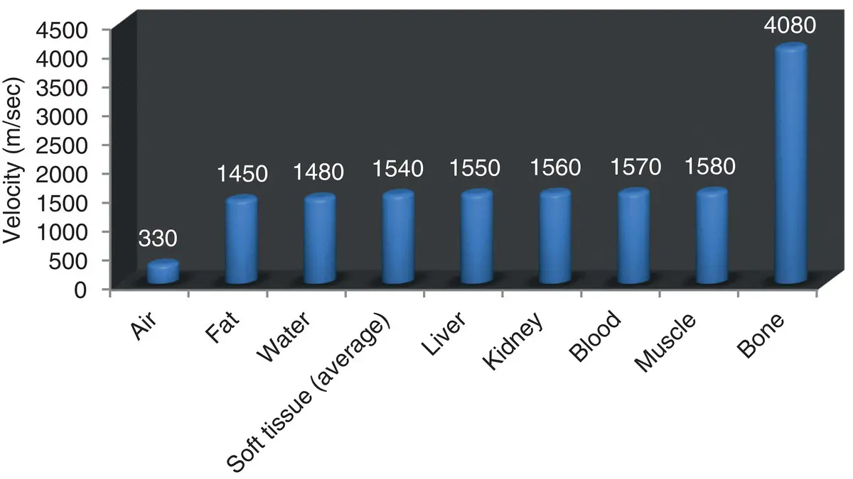
Figure 2.1. Velocity (m/sec) of sound through common body tissues or substances. Note the similar velocity through most soft tissues. This is the basis for using 1540 m/sec as the number in depth calculations by the ultrasound processor (Coltrera 2010).
Pearl:Remember the saying: Ultrasound hates bone or stone and is not too fair with air.
Acoustic Impedance
Acoustic impedance refers to the reflection and transmission characteristics of a substance. It is a measure of absorption of sound and the ratio of sound pressure at a boundary surface to the sound flux. Sound flux is flow velocity multiplied by area. If we draw an analogy to electronic circuits, acoustic impedance is like electrical resistance through a wire, sound pressure is like voltage, and flow velocity is like current. The equation that brings it all together is:

where Z = acoustic impedance, p = sound pressure (or tissue density), and v = velocity (Nyland 2002).
Читать дальшеИнтервал:
Закладка:
Похожие книги на «Point-of-Care Ultrasound Techniques for the Small Animal Practitioner»
Представляем Вашему вниманию похожие книги на «Point-of-Care Ultrasound Techniques for the Small Animal Practitioner» списком для выбора. Мы отобрали схожую по названию и смыслу литературу в надежде предоставить читателям больше вариантов отыскать новые, интересные, ещё непрочитанные произведения.


Обсуждение, отзывы о книге «Point-of-Care Ultrasound Techniques for the Small Animal Practitioner» и просто собственные мнения читателей. Оставьте ваши комментарии, напишите, что Вы думаете о произведении, его смысле или главных героях. Укажите что конкретно понравилось, а что нет, и почему Вы так считаете.