Malcolm J. Crocker - Engineering Acoustics
Здесь есть возможность читать онлайн «Malcolm J. Crocker - Engineering Acoustics» — ознакомительный отрывок электронной книги совершенно бесплатно, а после прочтения отрывка купить полную версию. В некоторых случаях можно слушать аудио, скачать через торрент в формате fb2 и присутствует краткое содержание. Жанр: unrecognised, на английском языке. Описание произведения, (предисловие) а так же отзывы посетителей доступны на портале библиотеки ЛибКат.

- Название:Engineering Acoustics
- Автор:
- Жанр:
- Год:неизвестен
- ISBN:нет данных
- Рейтинг книги:3 / 5. Голосов: 1
-
Избранное:Добавить в избранное
- Отзывы:
-
Ваша оценка:
Engineering Acoustics: краткое содержание, описание и аннотация
Предлагаем к чтению аннотацию, описание, краткое содержание или предисловие (зависит от того, что написал сам автор книги «Engineering Acoustics»). Если вы не нашли необходимую информацию о книге — напишите в комментариях, мы постараемся отыскать её.
Engineering Acoustics — читать онлайн ознакомительный отрывок
Ниже представлен текст книги, разбитый по страницам. Система сохранения места последней прочитанной страницы, позволяет с удобством читать онлайн бесплатно книгу «Engineering Acoustics», без необходимости каждый раз заново искать на чём Вы остановились. Поставьте закладку, и сможете в любой момент перейти на страницу, на которой закончили чтение.
Интервал:
Закладка:
(3.53) 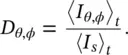
Figure 3.12 Geometry used in derivation of directivity factor.
For a directional source, the mean square sound pressure measured at distance r and angles θ and ϕ is p 2 rms( θ,ϕ ).
In the far field of this source ( r ≫ λ ), then
(3.54) 
But if the source were omnidirectional of the same power W , then
(3.55) 
where p 2 rmsis a constant, independent of angles θ and ϕ .
We may therefore write:
(3.56) 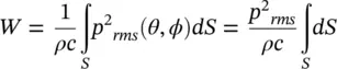
and
(3.57) 
where  is the space‐averaged mean‐square sound pressure.
We define the directivity factor Q as
(3.58) 
the ratio of the mean‐square sound pressure at distance r to the space‐averaged mean‐square pressure at r , or equivalently the directivity Q may be defined as the ratio of the mean‐square sound pressure at r divided by the mean‐square sound pressure at r for an omnidirectional sound source of the same sound power W , watts.
3.9.2 Directivity Index
The directivity index DI is just a logarithmic version of the directivity factor Q . It is expressed in decibels.
A directivity index DI θ,ϕmay be defined, where
(3.59) 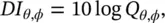
(3.60) 
Note if the source power remains the same when it is put on a hard rigid infinite surface Q ( θ , ϕ ) = 2 and DI ( θ , ϕ ) = 3 dB.
Example 3.11
1 If a constant‐volume velocity source of sound power level 120 dB (which is equivalent to 1 acoustic watt) radiates to whole space and it has a directivity factor of 12 at 50 m, what is the sound pressure level in that direction?
2 If this constant‐volume velocity source is put very near a hard reflecting floor, what will its sound pressure level be in the same direction?
Solution
1 We have that I = 1/4π(50)2 = 1/104 π (W/m2), then But for the directional source Lp(θ, ϕ) = 〈Lp〉S + DI(θ, ϕ), then assuming ρ c = 400 rayls, Lp(θ, ϕ) = 75 + 10 log 12 = 75 + 10 + 10 log 1.2 = 85.8 dB.
2 If the direction is away from the floor, then
3.10 Line Sources
Sometimes noise sources are distributed more like idealized line sources . Examples include the sound radiated from a long pipe containing fluid flow or the sound radiated by a stream of vehicles on a highway.
If sound sources are distributed continuously along a straight line and the sources are radiating sound independently, so that the sound power/unit length is W′ watts/metre, then assuming cylindrical spreading (and we are located in the far acoustic field again and ρc = 400 rayls):
(3.61) 
so,
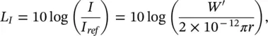
then
(3.62) 
and for half‐space radiation (such as a line source on a hard surface, such as a road)
(3.63) 
3.11 Reflection, Refraction, Scattering, and Diffraction
For a homogeneous plane sound wave at normal incidence on a fluid medium of different characteristic impedance ρc , both reflected and transmitted waves are formed (see Figure 3.13).
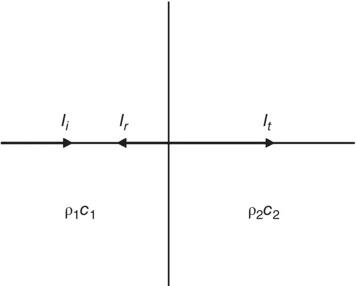
Figure 3.13 Incident intensity I i, reflected intensity I r, and transmitted intensity I tin a homogeneous plane sound wave at normal incidence on a plane boundary between two fluid media of different characteristic impedances.
From energy considerations (provided no losses occur at the boundary) the sum of the reflected intensity I rand transmitted intensity I tequals the incident intensity I i:
(3.64) 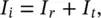
and dividing throughout by I i,
(3.65) 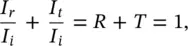
where R is the energy reflection coefficient and T is the transmission coefficient . For plane waves at normal incidence on a plane boundary between two fluids (see Figure 3.13):
(3.66) 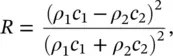
and
(3.67) 
Some interesting facts can be deduced from Eqs. (3.66)and (3.67). Both the reflection and transmission coefficients are independent of the direction of the wave since interchanging ρ 1 c 1and ρ 2 c 2does not affect the values of R and T . For example, for sound waves traveling from air to water or water to air, almost complete reflection occurs, independent of direction; the reflection coefficients are the same and the transmission coefficients are the same for the two different directions.
Читать дальшеИнтервал:
Закладка:
Похожие книги на «Engineering Acoustics»
Представляем Вашему вниманию похожие книги на «Engineering Acoustics» списком для выбора. Мы отобрали схожую по названию и смыслу литературу в надежде предоставить читателям больше вариантов отыскать новые, интересные, ещё непрочитанные произведения.


Обсуждение, отзывы о книге «Engineering Acoustics» и просто собственные мнения читателей. Оставьте ваши комментарии, напишите, что Вы думаете о произведении, его смысле или главных героях. Укажите что конкретно понравилось, а что нет, и почему Вы так считаете.