Malcolm J. Crocker - Engineering Acoustics
Здесь есть возможность читать онлайн «Malcolm J. Crocker - Engineering Acoustics» — ознакомительный отрывок электронной книги совершенно бесплатно, а после прочтения отрывка купить полную версию. В некоторых случаях можно слушать аудио, скачать через торрент в формате fb2 и присутствует краткое содержание. Жанр: unrecognised, на английском языке. Описание произведения, (предисловие) а так же отзывы посетителей доступны на портале библиотеки ЛибКат.

- Название:Engineering Acoustics
- Автор:
- Жанр:
- Год:неизвестен
- ISBN:нет данных
- Рейтинг книги:3 / 5. Голосов: 1
-
Избранное:Добавить в избранное
- Отзывы:
-
Ваша оценка:
Engineering Acoustics: краткое содержание, описание и аннотация
Предлагаем к чтению аннотацию, описание, краткое содержание или предисловие (зависит от того, что написал сам автор книги «Engineering Acoustics»). Если вы не нашли необходимую информацию о книге — напишите в комментариях, мы постараемся отыскать её.
Engineering Acoustics — читать онлайн ознакомительный отрывок
Ниже представлен текст книги, разбитый по страницам. Система сохранения места последней прочитанной страницы, позволяет с удобством читать онлайн бесплатно книгу «Engineering Acoustics», без необходимости каждый раз заново искать на чём Вы остановились. Поставьте закладку, и сможете в любой момент перейти на страницу, на которой закончили чтение.
Интервал:
Закладка:
and by taking 10 log throughout this equation
(3.50) 
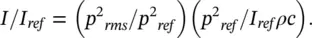
where L pis the sound pressure level, L Wis the source sound power level, and r is the distance, in metres, from the source center. (Note we have assumed here that ρc = 415 ≅400 rayls.) If ρc ≅ 400 rayls (kg/m 2s), then since I = p 2 rms/ ρc
So,
(3.51) 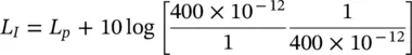
3.8 Sound Sources Above a Rigid Hard Surface
In practice many real engineering sources (such as machines and vehicles) are mounted or situated on hard reflecting ground and concrete surfaces. If we can assume that the source of sound power W radiates only to a half‐space solid angle 2 π , and no power is absorbed by the hard surface ( Figure 3.10), then
(3.52) 
where L Wis the sound power level of the source and r is the distance in metres.
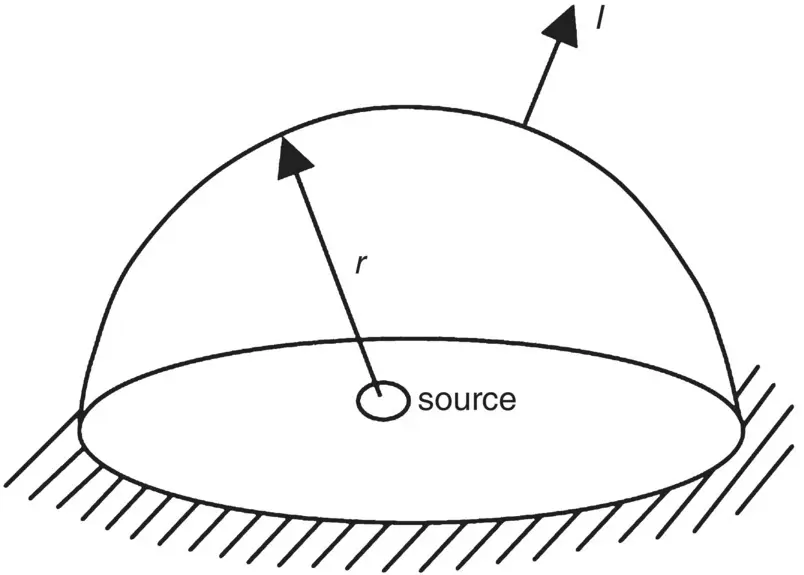
Figure 3.10 Source above a rigid surface.
In this discussion we have assumed that the sound source radiates the same sound intensity in all directions; that is, it is omnidirectional. If the source of sound power W becomes directional, the mean square sound pressure in Eqs. (3.48)and (3.46)will vary with direction, and the sound power W can only be obtained from Eqs. (3.41)and (3.47)by measuring either the mean‐square pressure ( p 2 rms) all over a surface enclosing the source (in the far acoustic field, the far field) and integrating Eq. (3.47)over the surface, or by measuring the intensity all over the surface in the near or far acoustic field and integrating over the surface ( Eq. (3.41)). We shall discuss source directivity in Section 3.9.
Example 3.10
If the sound power level of a source is 120 dB (which is equivalent to 1 acoustical watt), what is the sound pressure level at 50 m (a) for sound radiation to whole space and (b) for radiation to half space?
Solution
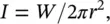
1 For whole space: I = 1/4π(50)2 = 1/104 π (W/m2), then
Since we may assume r = 50 m is in the far acoustic field, Lp ≅ LI = 75 dB as well (we have also assumed ρc ≅ 400 rayls).
For half space: I = 1/2π(50)2 = 2/104 π (W/m2), then
and L p≅ L I= 78 dB also.
It is important to note that the sound power radiated by a source can be significantly affected by its environment. For example, if a simple constant‐volume velocity source (whose strength Q will be unaffected by the environment) is placed on a floor, its sound power will be doubled (and its sound power level increased by 3 dB). If it is placed at a floor–wall intersection, its sound power will be increased by four times (6 dB); and if it is placed in a room comer, its power is increased by eight times (9 dB). See Table 3.2. Many simple sources of sound (ideal sources, monopoles, and real small machine sources) produce more sound power when put near reflecting surfaces, provided their surface velocity remains constant. For example, if a monopole is placed touching a hard plane, an image source of equal strength may be assumed.
Table 3.2 Simple source near reflecting surfaces a.
| Intensity | Source | Condition | Number of Images |  |
Power | D | DI |
|---|---|---|---|---|---|---|---|
| I |  |
Free field | None |  |
W | 1 | 0 dB |
| 4 I | 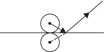 |
Reflecting plane | 1 |  |
2 W | 4 | 6 dB |
| 16 I | 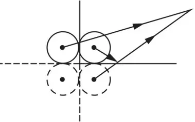 |
Wall‐floor intersection | 3 |  |
4 W | 16 | 12 dB |
| 64 I | 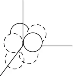 |
Room corner | 7 |  |
8 W | 64 | 18 dB |
a Q and DI are defined in Eqs. (3.53), (3.58), and (3.60).
3.9 Directivity
The sound intensity radiated by a dipole is seen to depend on cos 2 θ (see Figure 3.11). Most real sources of sound become directional at high frequency, although some are almost omnidirectional at low frequency. This phenomenon depends on the source dimension, d , which must be small in size compared with a wavelength λ , so d/λ ≪ 1 for them to behave almost omnidirectionally.

Figure 3.11 Polar directivity plots for the radial sound intensity in the far field of (a) monopole, (b) dipole, and (c) (lateral) quadrupole.
3.9.1 Directivity Factor ( Q ( θ , ϕ ))
In general, a directivity factor Q θ,ϕmay be defined as the ratio of the radial intensity 〈 I θ, ϕ〉 t(at angles θ and ϕ and distance r from the source) to the radial intensity 〈 I s〉 tat the same distance r radiated from an omnidirectional source of the same total sound power ( Figure 3.12). Thus
Читать дальшеИнтервал:
Закладка:
Похожие книги на «Engineering Acoustics»
Представляем Вашему вниманию похожие книги на «Engineering Acoustics» списком для выбора. Мы отобрали схожую по названию и смыслу литературу в надежде предоставить читателям больше вариантов отыскать новые, интересные, ещё непрочитанные произведения.


Обсуждение, отзывы о книге «Engineering Acoustics» и просто собственные мнения читателей. Оставьте ваши комментарии, напишите, что Вы думаете о произведении, его смысле или главных героях. Укажите что конкретно понравилось, а что нет, и почему Вы так считаете.