James C. Kessler - Fundamentals of Fixed Prosthodontics
Здесь есть возможность читать онлайн «James C. Kessler - Fundamentals of Fixed Prosthodontics» — ознакомительный отрывок электронной книги совершенно бесплатно, а после прочтения отрывка купить полную версию. В некоторых случаях можно слушать аудио, скачать через торрент в формате fb2 и присутствует краткое содержание. Жанр: unrecognised, на английском языке. Описание произведения, (предисловие) а так же отзывы посетителей доступны на портале библиотеки ЛибКат.
- Название:Fundamentals of Fixed Prosthodontics
- Автор:
- Жанр:
- Год:неизвестен
- ISBN:нет данных
- Рейтинг книги:3 / 5. Голосов: 1
-
Избранное:Добавить в избранное
- Отзывы:
-
Ваша оценка:
Fundamentals of Fixed Prosthodontics: краткое содержание, описание и аннотация
Предлагаем к чтению аннотацию, описание, краткое содержание или предисловие (зависит от того, что написал сам автор книги «Fundamentals of Fixed Prosthodontics»). Если вы не нашли необходимую информацию о книге — напишите в комментариях, мы постараемся отыскать её.
Fundamentals of Fixed Prosthodontics — читать онлайн ознакомительный отрывок
Ниже представлен текст книги, разбитый по страницам. Система сохранения места последней прочитанной страницы, позволяет с удобством читать онлайн бесплатно книгу «Fundamentals of Fixed Prosthodontics», без необходимости каждый раз заново искать на чём Вы остановились. Поставьте закладку, и сможете в любой момент перейти на страницу, на которой закончили чтение.
Интервал:
Закладка:
The facebow is attached to the maxillary teeth, and the side arms are adjusted so that the pin at the free (posterior) end of each side arm will touch the hinge axis mark on its respective side of the face ( Fig 3-9). A third reference point is selected on the face and recorded by adjusting a pointer on the facebow. The facebow is removed from the patient and transferred to the articulator. The reference pins on the facebow are placed over the axis of rotation on the articulator condyles. With the anterior reference device providing the vertical orientation of the facebow, it can then be used to accurately mount the maxillary cast on the articulator. This technique is most commonly used for facebow transfers to fully adjustable articulators.
A facebow that employs an approximate location of the hinge axis based on an anatomical average can also be used. This technique should provide enough accuracy for the restoration of most mouths, if the occlusal vertical dimension is not to be altered to any significant extent. An error of 5.0 mm in the location of the THA will produce a negligible antero-posterior mandibular displacement of approximately 0.2 mm when a 3.0-mm centric relation record is removed to close the articulator. 4
Table 3-1 Accuracy of arbitrary hinge axis points*
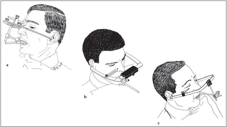
Fig 3-10Three caliper-style facebows among those in use at the present time: (a) QuickMount (Whip Mix); (b) Denar Slidematic (Whip Mix); (c) Hanau Spring-Bow (Whip Mix).
There are numerous techniques used for arbitrarily locating the hinge axis to serve as the set of posterior reference points for a facebow. 6–14A comparison of the accuracy of arbitrary and kinematically located hinge axis points is shown in Table 3-1.
Facebows must have acceptable accuracy and be simple to apply or they will not be used routinely. Caliper-style ear facebows possess a relatively high degree of accuracy, with 75% of the axes located by it falling within 6 mm of the true hinge axis. 12There are several caliper-style facebows ( Fig 3-10). They are designed to be self-centering so that little time is wasted in centering the bite fork and adjusting individual side arms. The technique for their use is described in chapter 4.
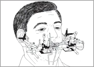
Fig 3-11An air-activated pantograph for recording mandibular movements.
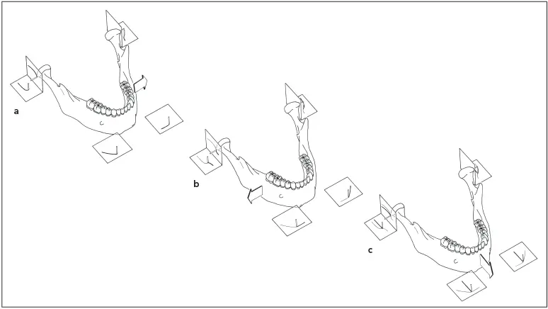
Fig 3-12Tracings are shown for a pantograph in which all recording tables are attached to the mandible and all styli are attached to the maxilla. Styli are shown in their initial positions. (a) Left lateral excursion; (b) right lateral excursion; (c) protrusive excursion.
Registration of Condylar Movements
To faithfully simulate the condylar movement on an articulator, it is necessary to obtain a precise tracing of the paths followed by the condyle. This can be achieved most accurately by means of a pantographic recording, which will capture all of the characteristics of the mandibular border movement from its optimum position to its most forward and most lateral positions.
The pantograph consists of two facebows. One is affixed to the maxilla and the other to the mandible, using clutches that attach to the teeth in the respective arches. Recording styli are attached to the one member, and small tables upon which the tracings are made are attached to the other member of the instrument, opposite the styli. There are both horizontal and vertical posterior tables attached in the vicinity of the hinge axis on each side of the pantograph. There are also two tables attached to the anterior member of the bow, one on either side of the midline ( Fig 3-11).
The mandible goes through a series of right and left lateral, as well as protrusive, excursions. The styli on one facebow scribe on the recording tables the paths followed by the condyles in each movement ( Fig 3-12). When the pantograph is attached to the articulator, various adjustments are made until the movements of the articulator will follow the same paths scribed on the tracings during mandibular excursions.
The pantographic tracing can only be utilized to full advantage when used with a fully adjustable articulator. To adjust the settings of a semi-adjustable articulator, wax interocclusal records are used. The patient closes into a heatsoftened wax wafer in a right lateral protrusive position and maintains that posture until the wax has hardened. The procedure is repeated with another wax wafer for a left lateral protrusive position. The wax wafers are then placed, first one and then the other, on the articulated casts. After the right lateral wafer is used to adjust the condylar inclination for the left condyle, the left lateral wafer is used to adjust the right condylar inclination. Complete details of the technique are described in chapter 4.
Advances in electronics and computers have brought about the introduction of new electronic pantographs that determine the condylar settings of the articulator. One type of electronic pantograph is similar to a traditional pantograph, with the styli and recording tables replaced by electronic senders and receivers. Another type utilizes a sender unit located at the end of a bite fork that is attached to the mandibular teeth. A receiver unit is suspended from a facebow mechanism directly above it. With both types of instruments, as the patient moves the mandible through the border movements, information is recorded and displayed on a small computer. This information can then be used to adjust the condylar settings on a fully adjustable or semi-adjustable articulator.
References
1. Posselt U. Physiology of Occlusion and Rehabilitation, ed 2. Oxford: Blackwell Scientific, 1968:55.
2. Hobo S, Shillingburg HT Jr, Whitsett LD. Articulator selection for restorative dentistry. J Prosthet Dent 1976;36:35–43.
3. Hodge LC, Mahan PE. A study of mandibular movement from centric occlusion to maximum intercuspation. J Prosthet Dent 1967;18:19–30.
4. Weinberg LA. An evaluation of the face-bow mounting. J Prosthet Dent 1961;11:32–42.
5. McCollum BB, Stuart CE. Gnathology—A Research Report. South Pasadena, CA: Scientific Press, 1955:39.
6. Kornfeld M. Mouth Rehabilitation: Clinical and Laboratory Procedures, ed 2. St Louis: Mosby, 1974:48,336.
7. Schallhorn RG. A study of the arbitrary center and the kinematic center of rotation for face-bow mountings. J Prosthet Dent 1957;7:162–169.
8. Beyron H. Orienteringsproblem vid protetiska rekonstruktioner och bettstudier. Sven Tandlak Tidskr 1942;35:1–55.
9. Beck HO. A clinical evaluation of the arcon concept of articulation. J Prosthet Dent 1959;9:409–421.
10. Lauritzen AG, Bodner GH. Variations in location of arbitrary and true hinge axis points. J Prosthet Dent 1961;11:224–229.
11. Gysi A. The problem of articulation. Dent Cosmos 1910;52:1–19.
12. Teteruck WR, Lundeen HC. The accuracy of an ear face-bow. J Prosthet Dent 1966;16:1039–1046.
13. Bergstrom G. On the reproduction of dental articulation by means of articulators—A kinematic investigation. Acta Odontol Scand Suppl 1950;9(suppl 4):1–131.
14. Guichet NF. Procedures for Occlusal Treatment—A Teaching Atlas. Anaheim, CA: Denar, 1969:35.
Читать дальшеИнтервал:
Закладка:
Похожие книги на «Fundamentals of Fixed Prosthodontics»
Представляем Вашему вниманию похожие книги на «Fundamentals of Fixed Prosthodontics» списком для выбора. Мы отобрали схожую по названию и смыслу литературу в надежде предоставить читателям больше вариантов отыскать новые, интересные, ещё непрочитанные произведения.


Обсуждение, отзывы о книге «Fundamentals of Fixed Prosthodontics» и просто собственные мнения читателей. Оставьте ваши комментарии, напишите, что Вы думаете о произведении, его смысле или главных героях. Укажите что конкретно понравилось, а что нет, и почему Вы так считаете.