Katherine Kula - Cephalometry in Orthodontics
Здесь есть возможность читать онлайн «Katherine Kula - Cephalometry in Orthodontics» — ознакомительный отрывок электронной книги совершенно бесплатно, а после прочтения отрывка купить полную версию. В некоторых случаях можно слушать аудио, скачать через торрент в формате fb2 и присутствует краткое содержание. Жанр: unrecognised, на английском языке. Описание произведения, (предисловие) а так же отзывы посетителей доступны на портале библиотеки ЛибКат.
- Название:Cephalometry in Orthodontics
- Автор:
- Жанр:
- Год:неизвестен
- ISBN:нет данных
- Рейтинг книги:4 / 5. Голосов: 1
-
Избранное:Добавить в избранное
- Отзывы:
-
Ваша оценка:
Cephalometry in Orthodontics: краткое содержание, описание и аннотация
Предлагаем к чтению аннотацию, описание, краткое содержание или предисловие (зависит от того, что написал сам автор книги «Cephalometry in Orthodontics»). Если вы не нашли необходимую информацию о книге — напишите в комментариях, мы постараемся отыскать её.
Cephalometry in Orthodontics — читать онлайн ознакомительный отрывок
Ниже представлен текст книги, разбитый по страницам. Система сохранения места последней прочитанной страницы, позволяет с удобством читать онлайн бесплатно книгу «Cephalometry in Orthodontics», без необходимости каждый раз заново искать на чём Вы остановились. Поставьте закладку, и сможете в любой момент перейти на страницу, на которой закончили чтение.
Интервал:
Закладка:
CCD/CMOS receptors
Direct digital cephalometric x-ray machines use either a CCD or CMOS receptor for image capture. While these two types of digital receptor differ with regard to image capture and data transfer, both generate comparable images. Some panoramic cephalometric combination machines use only one sensor that has to be moved depending on the type of image captured. Other combination machines use two sensors, which is much more efficient and decreases the risk of damaging the sensor by dropping it. The majority of these units capture an image in a scanning motion either horizontally or vertically ( Figs 2-5and 2-6). This type of image capture differs from film-based and PSP imaging, which capture the image in a single exposure. Image capture with the scanning motion requires the patient to remain motionless for up to 10 seconds. The possibility for motion artifact increases as the exposure (or in this case scanning) time increases. At least two companies (Carestream and Vatech) have produced a “one-shot” image capture system that potentially can create the same projection geometry as conventional cephalometry while significantly decreasing the time the patient must remain motionless.
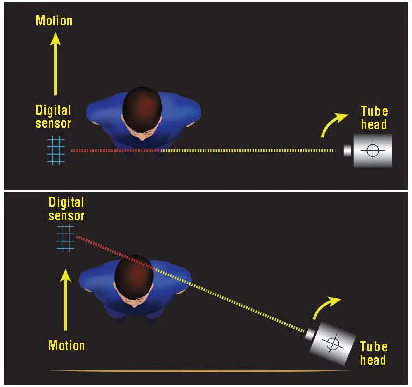
Fig 2-5Graphic representation of scanning motion for direct digital cephalometric units.
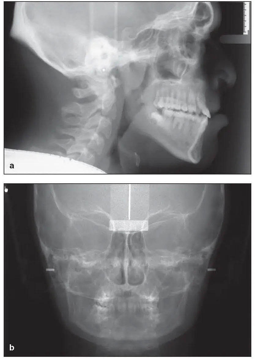
Fig 2-6Examples of direct digital (scanned) lateral (a) and PA (b) cephalograms.
Digital Versus Conventional Cephalometry
Not all digital cephalometric images are the same. Cephalometric images captured on a PSP plate have the same projection geometry used to capture a film-based image. The majority of digital receptors, however, capture the image with a scanning motion and therefore have different magnification factors than in film-based cephalometry. Chadwick et al reported differences among several different systems that appear to be system dependent and recommended that the magnification factor be experimentally determined prior to any cephalometric analysis. 8McClure et al compared digital cephalometry with film-based cephalometry and found no differences in linear measurements; however, in their study, pretreatment cephalograms were compared with posttreatment cephalograms. 9The time frame between pre- and posttreatment images may introduce the confounder of active growth during the orthodontic treatment.
CBCT
CBCT began to appear in the late 1990s. CBCT machines consist of a radiation source shaped like a cone and a solid-state detector that rotates around the patient’s head and captures all of the scan data in a single rotation. 10This raw data is then reconstructed in the coronal, axial, and sagittal planes (also known as multiplanar reformation ) ( Fig 2-7). The data can be further reconstructed to produce either 2D images such as panoramic or cephalometric images ( Fig 2-8) or 3D data sets 11( Fig 2-9). The images produced with CBCT are not magnified, so standard cephalometric analysis must be altered to address this difference in projection geometry.

Fig 2-7Multiplanar reformation.
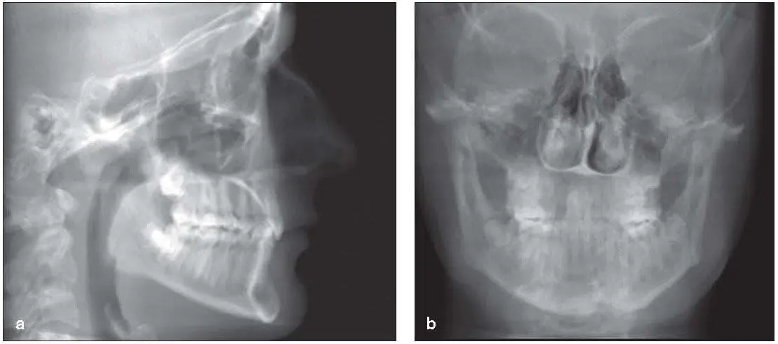
Fig 2-8Examples of CBCT-derived lateral (a) and PA (b) cephalograms.
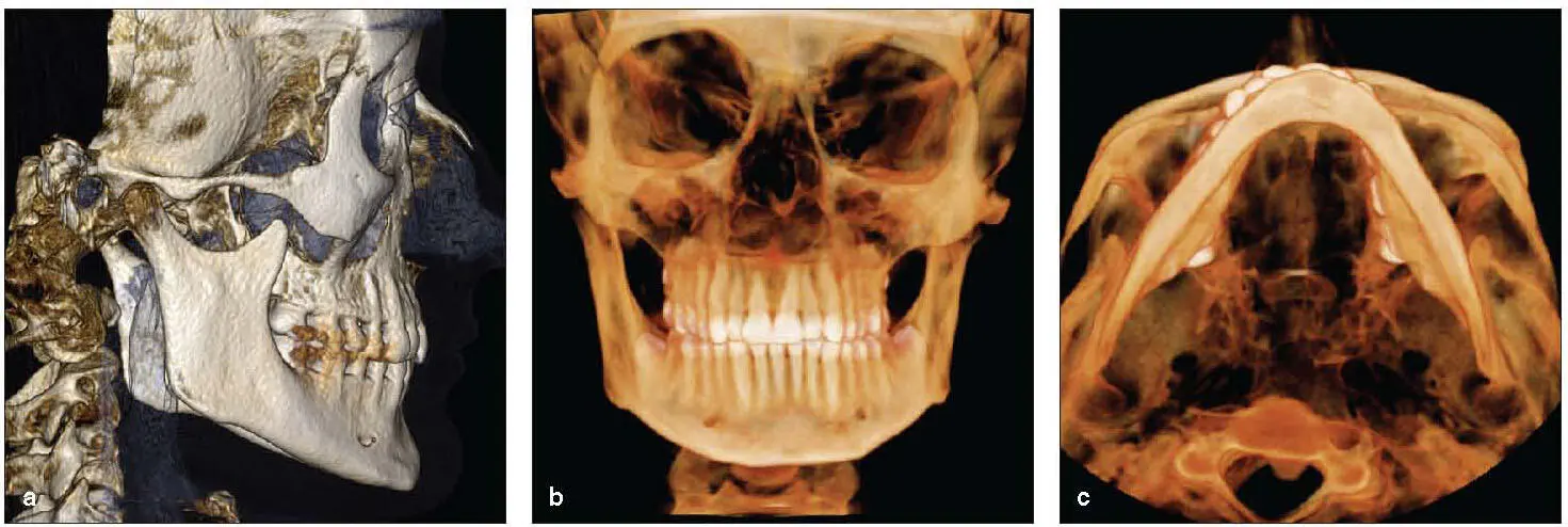
Fig 2-9Examples of 3D reconstructions. (a) Lateral cephalometric rendering. (b) PA cephalometric rendering. (c) Submentovertex rendering.
While the name implies similarity with conventional CT, the two technologies differ in a number of ways. The most important difference for the patient is the difference in dose. Conventional CT produces a four- to tenfold higher dose than CBCT when imaging the maxillofacial region. 6There are several reasons for this difference in dose, but the fundamental difference is that CBCT captures the entire data set in one rotation, whereas conventional CT requires multiple rotations to capture the data. This single rotation decreases the dose but also is more susceptible to patient motion. If the patient moves during conventional CT imaging, only that slice of data is impacted. However, patient movement affects every voxel during CBCT image capture. Another difference has to do with the imaging of soft tissue. Conventional CT uses a high mA, which contributes to the soft tissue contrast; CBCT uses a fairly low mA, with minimal soft tissue contrast. CBCT will capture soft tissue, but the soft tissue is displayed as a fairly homogenous image.
Selection criteria
CBCT can provide a wealth of information regarding the maxillofacial regions. The ability to generate 3D images greatly enhances the treatment-planning process for many patients but may be unnecessary for some patients. The decision to scan or not to scan will be dependent on the patient’s condition. The delineation of whom to scan is called selection criteria . In 2013, the American Academy of Oral and Maxillofacial Radiology published clinical recommendations for the use of CBCT in orthodontics. 12The first recommendation is to use the appropriate imaging modality based on the patient’s clinical presentation and history. 12The second recommendation pertains to radiation risk assessment, and the third recommendation addresses ways to keep the dose to the patient as low as reasonably achievable (ALARA), 12such as focusing on resolution, scan time, and field of view (FOV).
Scanning protocol
Because the goal in orthodontic imaging is to get the best data with the lowest dose to the patient, several factors should be included in the scanning protocol. The first consideration is the volume of the scan. Volume will be dictated by the choice of the FOV. The larger the FOV, the higher the dose to the patient. Keeping the FOV as small as possible will minimize the dose to the patient. Determining resolution requirements is another way to diminish dose to the patient. Generally, the higher the resolution, the higher the dose. Using the lowest resolution that still provides adequate diagnostic information is a good way to decrease the dose to the patient. Finally, the last consideration is exposure time. As with any radiographic imaging, the longer the exposure time, the higher the dose. Therefore, the shortest scan time that provides adequate diagnostic information should be used. The imaging protocol should address all of these parameters.
Patient positioning and preparation
The patient should be draped with a lap apron for image acquisition. Patient positioning differs with every commercially available scanner. Some systems capture the image with the patient standing, while others capture the image with the patient seated. Regardless of manufacturer, all units provide some form of head stabilization. It is important to position the patient’s head with the Frankfort plane parallel to the floor and the midsagittal plane perpendicular to the floor. While the position of the head can be altered during the image-reconstruction process, the same cannot be said for the cervical spine. Many CBCT scanners provide a bite stick for patient positioning. The bite stick produces an end-to-end occlusion that can alter the width of the airway and the condyle/fossa relationship. The use of the bite stick should therefore be avoided.
Читать дальшеИнтервал:
Закладка:
Похожие книги на «Cephalometry in Orthodontics»
Представляем Вашему вниманию похожие книги на «Cephalometry in Orthodontics» списком для выбора. Мы отобрали схожую по названию и смыслу литературу в надежде предоставить читателям больше вариантов отыскать новые, интересные, ещё непрочитанные произведения.


Обсуждение, отзывы о книге «Cephalometry in Orthodontics» и просто собственные мнения читателей. Оставьте ваши комментарии, напишите, что Вы думаете о произведении, его смысле или главных героях. Укажите что конкретно понравилось, а что нет, и почему Вы так считаете.