Katherine Kula - Cephalometry in Orthodontics
Здесь есть возможность читать онлайн «Katherine Kula - Cephalometry in Orthodontics» — ознакомительный отрывок электронной книги совершенно бесплатно, а после прочтения отрывка купить полную версию. В некоторых случаях можно слушать аудио, скачать через торрент в формате fb2 и присутствует краткое содержание. Жанр: unrecognised, на английском языке. Описание произведения, (предисловие) а так же отзывы посетителей доступны на портале библиотеки ЛибКат.
- Название:Cephalometry in Orthodontics
- Автор:
- Жанр:
- Год:неизвестен
- ISBN:нет данных
- Рейтинг книги:4 / 5. Голосов: 1
-
Избранное:Добавить в избранное
- Отзывы:
-
Ваша оценка:
Cephalometry in Orthodontics: краткое содержание, описание и аннотация
Предлагаем к чтению аннотацию, описание, краткое содержание или предисловие (зависит от того, что написал сам автор книги «Cephalometry in Orthodontics»). Если вы не нашли необходимую информацию о книге — напишите в комментариях, мы постараемся отыскать её.
Cephalometry in Orthodontics — читать онлайн ознакомительный отрывок
Ниже представлен текст книги, разбитый по страницам. Система сохранения места последней прочитанной страницы, позволяет с удобством читать онлайн бесплатно книгу «Cephalometry in Orthodontics», без необходимости каждый раз заново искать на чём Вы остановились. Поставьте закладку, и сможете в любой момент перейти на страницу, на которой закончили чтение.
Интервал:
Закладка:
17.Riedal R. An analysis of dentofacial relationships. Am J Orthod 1957;43:103–119.
18.Casko JS, Shepherd WB. Dental and skeletal variation within the range of normal. Angle Orthod 1984;54:5–17.
19.Downs WB. Variations in facial relationships: Their significance in treatment prognosis. Am J Orthod 1948;34:812–840.
20.Kula TJ III, Ghoneima A, Eckert G, Parks E, Utreja A, Kula K. A 2D vs 3D comparison of alveolar bone over maxillary incisors using A point as a reference. Am J Orthod Dentofacial Orthopedics (in press).
21.Gribel BF, Gribel MN, Frazão DC, McNamara Jr JA, Manzi FR. Accuracy and reliability of craniometric measurements on lateral cephalometry and 3D measurements on CBCT scans. Angle Orthod 2011;81:26–35.
22.Steiner CC. Cephalometrics for you and me. Am J Orthod 1953;39:729–754.
23.Markets and Markets. CBCT/Cone Beam Imaging Market by Application. http://www.marketsandmarkets.com/Market-Reports/cone-beam-imaging-market-226049013.html?gclid=EAIaIQobChMI4_b899b31AIVyEwNCh1xXQseEAAYASAAEgJa0_D_BwE. Accessed 25 August 2017.
2
2D and 3D Radiography
Edwin T. Parks, DMD, MS
Two-dimensional (2D) cephalometry has been an integral component of orthodontic patient assessment since Broadbent described the technique in 1931. 1For years the only image receptor for cephalometry was radiographic film, which limited the clinician to a 2D patient assessment. Today there are multiple receptor options such as photostimulable phosphor (PSP), charge-coupled device (CCD), and derived 2D data from cone beam computed tomography (CBCT). While CBCT allows for clinicians to evaluate the patient in three dimensions, most patient assessment is still performed on 2D data. This chapter discusses the various techniques for generating traditional 2D cephalograms, cephalograms derived from three-dimensional (3D) data, radiation exposures, and advantages/disadvantages of the various techniques and image receptors.
Patient Positioning
Regardless of image receptor, proper patient positioning is essential to producing an acceptable cephalometric image.
Lateral cephalogram
The patient’s head is positioned with the left side of the face next to the image receptor, with the midsagittal plane parallel to the image receptor and the Frankfort plane parallel to the floor 2( Fig 2-1). The patient’s head should be stabilized in a cephalostat. The cephalostat is a device with two ear rods that are placed in the external auditory meatuses and a nasion guide. Head stabilization serves two purposes: (1) It diminishes patient movement, and (2) it ensures reproducibility to allow for sequential evaluation over time.
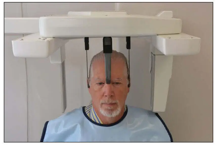
Fig 2-1Proper patient positioning for a lateral cephalogram showing the cephalostat around the patient’s head.
The radiation source is positioned so that the distance between the source and the midsagittal plane is 60 inches. The receptor (or film) should be placed 15 cm (approximately 6 inches) from the midsagittal plane. The x-ray beam should be collimated to the size of the receptor, and the center of the beam should be directed through the external auditory meatus ( Fig 2-2). Because of the projection geometry, structures away from the receptor will be magnified more than the structures close to the receptor.
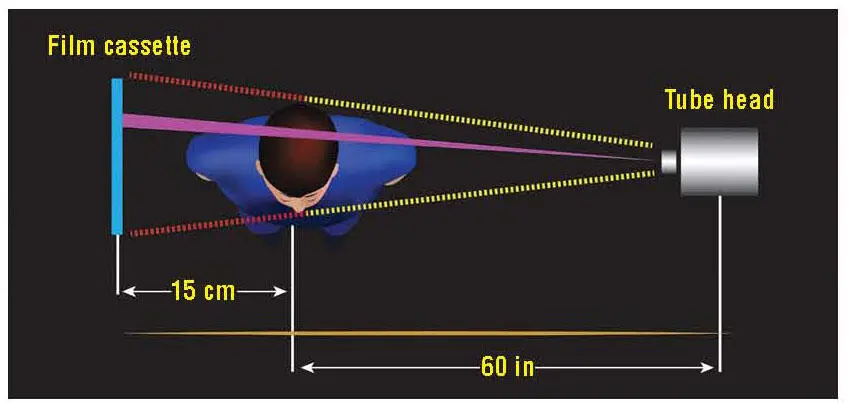
Fig 2-2Graphic representation of patient positioning for a lateral cephalogram (viewed from above) .
Posteroanterior cephalogram
Patient positioning for the posteroanterior (PA) cephalogram uses the same armamentarium as the lateral cephalogram. The patient is positioned with the midsagittal plane perpendicular to the receptor (nose toward the receptor) and the Frankfort plane parallel to the floor ( Fig 2-3). The source should be 60 inches from the ear rods, and the receptor should be positioned 15 cm from the ear rods. 2
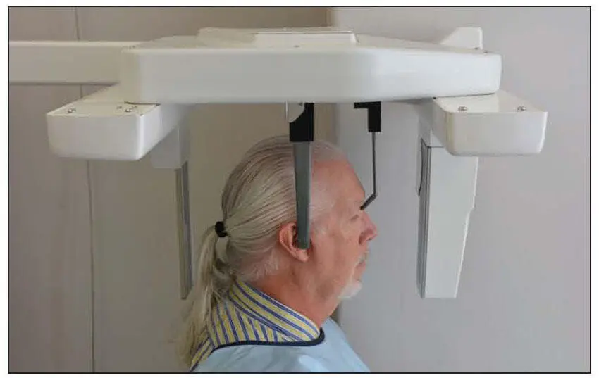
Fig 2-3Proper patient positioning for a PA cephalogram.
Patient Protection
There has been a great deal of discussion regarding the need for shielding of the patient from the primary beam. The American Dental Association, 3National Council on Radiation Protection and Measurements, 4and US Food and Drug Administration 3have created fairly specific recommendations for patient shielding for intraoral imaging but not for extraoral imaging. Nevertheless, many of the factors involved in the recommendations are applicable to extraoral imaging. Use of fast image receptors and collimation of the primary beam to the size of the receptor significantly reduce the dose to the patient. However, these factors do not reduce the dose to zero. Consequently, there is slight potential for risk to the patient.
The effects of high doses of x-radiation are well documented, but the effects of low doses of radiation have only been inferred or derived from a model. The accepted model for determining risk from x-radiation is the linear, nonthreshold model. This model suggests that risk is directly related to radiation dose. The concept of threshold is that there is a level of exposure below which there is no risk. The nonthreshold model indicates that there is no safe dose of radiation to the patient. Ludlow et al calculated effective doses for commonly used dental radiographic examinations and reported effective doses of 5.6 microsieverts (μSv) for a lateral cephalogram (using PSP) and 5.1 μSv for the PA cephalogram (using PSP). 5For comparison, they reported an effective dose for panoramic imaging (CCD) ranging from 14.2 to 24.3 μSv and 170.7 μSv for a full-mouth series using F-speed film and round collimation. 5In a different study, Ludlow et al evaluated the effective dose from several CBCT systems and reported effective doses ranging from 58.9 to 557.6 μSv. 6For a comparison, the paper also reported an effective dose for conventional CT of 2,100 μSv for a maxillomandibular scan. 6
There is a huge range of effective doses for these imaging modalities for many reasons. First, all of these systems use different exposure factors (eg, kilovoltage peak [kVp], milliamperage [mA], exposure time) and cover many different critical organs. The critical organs most commonly included in dose calculation for the maxillofacial complex are the thyroid gland, salivary glands, and bone marrow. This gets complicated pretty quickly. Now imagine what it must be like for the patient and parent when you start to describe effective dose. A better way to talk to the patient and parent is the concept of benefit versus risk. Explain to the patient and/or parent the reason you need the radiographic image (eg, asymmetry, impacted teeth) and that the risk to the patient is minimal. There is even some research that indicates that the lap apron provides no added protection from scatter radiation. 7This study, while not directly applicable, looks at the imaging modality that most closely approximates the field of view for orthodontic evaluation (panoramic). Still, it is important to realize that patients and parents are concerned about any radiation exposure. It probably takes less time to shield the patient with a lap apron than to explain why you do not need it. The thyroid collar should not be used for either 2D cephalometry or 3D CBCT.
Exposure Factors
Читать дальшеИнтервал:
Закладка:
Похожие книги на «Cephalometry in Orthodontics»
Представляем Вашему вниманию похожие книги на «Cephalometry in Orthodontics» списком для выбора. Мы отобрали схожую по названию и смыслу литературу в надежде предоставить читателям больше вариантов отыскать новые, интересные, ещё непрочитанные произведения.


Обсуждение, отзывы о книге «Cephalometry in Orthodontics» и просто собственные мнения читателей. Оставьте ваши комментарии, напишите, что Вы думаете о произведении, его смысле или главных героях. Укажите что конкретно понравилось, а что нет, и почему Вы так считаете.