Digital Workflow in Reconstructive Dentistry
Здесь есть возможность читать онлайн «Digital Workflow in Reconstructive Dentistry» — ознакомительный отрывок электронной книги совершенно бесплатно, а после прочтения отрывка купить полную версию. В некоторых случаях можно слушать аудио, скачать через торрент в формате fb2 и присутствует краткое содержание. Жанр: unrecognised, на английском языке. Описание произведения, (предисловие) а так же отзывы посетителей доступны на портале библиотеки ЛибКат.
- Название:Digital Workflow in Reconstructive Dentistry
- Автор:
- Жанр:
- Год:неизвестен
- ISBN:нет данных
- Рейтинг книги:4 / 5. Голосов: 1
-
Избранное:Добавить в избранное
- Отзывы:
-
Ваша оценка:
Digital Workflow in Reconstructive Dentistry: краткое содержание, описание и аннотация
Предлагаем к чтению аннотацию, описание, краткое содержание или предисловие (зависит от того, что написал сам автор книги «Digital Workflow in Reconstructive Dentistry»). Если вы не нашли необходимую информацию о книге — напишите в комментариях, мы постараемся отыскать её.
Contributors
Amirah M. R. Alammar • Abdulaziz Alsahaf • Wael Att • Maria Bateli • Jasmin Bernhart • Shaza Bishti • Sarah Blattner • Miha Brezavšček • Sandy Cepa • Nadine Emmanoulidi • Ahmed Fawzy • Manrique Fonseca • Michele Frapporti • Rumpa Ganguly • Yousef Al-Ghamdi • Petra Ch. Gierthmuehlen • Aiste Gintaute • Ulrich Lamott • Christos Lamprinos • Matthias Petsch • Udo Plaster • Aikaterini Ploumaki • Hanna Rauberger • Elisabeth Schwartzkopff • Christian F. Selz • Thamer Al-Sharif • Benedikt Spies • Frank A. Spitznagel • Jörg R. Strub • Michael Swain • Taskin Tuna • Alexander Vuck • Siegbert Witkowski
Digital Workflow in Reconstructive Dentistry — читать онлайн ознакомительный отрывок
Ниже представлен текст книги, разбитый по страницам. Система сохранения места последней прочитанной страницы, позволяет с удобством читать онлайн бесплатно книгу «Digital Workflow in Reconstructive Dentistry», без необходимости каждый раз заново искать на чём Вы остановились. Поставьте закладку, и сможете в любой момент перейти на страницу, на которой закончили чтение.
Интервал:
Закладка:
An alternative technique has also been developed that exclusively utilizes scan bodies from Biomet 3i. Once stone casts are created and mounted in an articulator, they are sent to the manufacturer for scanning. An individualized anatomical abutment can then be designed via CAD and milled from a solid Ti or ZrO 2block via CAM. 46,47The implant analog is placed in the definitive cast by a specialized robotic device (Robocast Technology, Zimmer Biomet) and sent back to the dental lab for fabrication of the restoration. Using this type of scan body, a second implant-level impression is not necessary, and the need to remove the healing abutment upon delivery of the definitive restoration is also eliminated. 42,45
In addition to the aforementioned techniques, the Cerec AC allows implant CAI either with the aid of a prefabricated abutment or a scan-compatible coping. In the first case, the clinician must modify and prepare a stock abutment and then follow the conventional chairside digital impression protocol. Once the crown design is performed using the Cerec AC software, the data is sent to the inLab MC XL (Sirona Dental Systems) for milling. In the second case, in which the use of a scan-compatible coping is planned, Sirona offers two options: the TiBase and ScanPost abutments combined with a proprietary scan body for a cemented or screw-retained final crown, respectively. In these cases and after the optical impression, the clinician sends the scan data to the laboratory, where the design and milling of the definitive superstructure will take place using the Cerec inLab. For screw-retained restorations, Sirona has launched specific monolithic lithium disilicate (LiSi 2) blocks with a canal for the future screw access hole. 43, 48
The implant CAI can be performed without any special tissue management for restorations located in the posterior segments, where esthetics is not the most critical issue. 49In the esthetic zone, on the other hand, soft tissue management by means of a screw-retained provisional is of great importance for achieving an optimal emergence profile and an esthetic result. Two techniques have been described to optically capture the emergence profile. In the first, after the removal of the temporary abutment, a scan body is screwed onto the implant and a digital impression is taken, simultaneously capturing the implant position and the surrounding soft tissue together with the emergence profile. 44For the second option, the optical impression is taken in two steps: initially, the optimally shaped emergence profile is scanned; then, a second scan is performed while the scan-compatible impression coping is tried-in to determine the 3D position of the implant. Afterwards the scan data are matched and a proposal for the final abutment design is generated using CAD software. 50
Regarding the accuracy of digital implant impressions, encouraging clinical results have emerged in terms of restoration with single implants. 51The accuracy of implant CAI can be affected by several factors, such as the degree of implant angulation, 52-54the distance between implants, 55and the implant level and depth. 53,54, 56
Moreover, implant CAI has been evaluated as a more time-efficient approach than the conventional impression method for single-implant rehabilitation by both in vitro and clinical studies. 41,57,58
Implant Planning Using CAI
Alongside the development of CAI, the development of cone-beam computed tomography (CBCT) enabled the generation of accurate 3D representations of the osseous jaw anatomy. Several contemporary CAD/CAM systems can work well with CBCT, providing thorough diagnostic data which can be combined, thereby enhancing the implant planning process. The oral and dental surface data sets, as well as the radiographic details, are obtained by using IOS and CBCT systems, respectively. The combination of these data sets requires compatibility between the IOS software and the implant planning software package, in which the common data points are matched ( Fig 2.10). Once the matching (superimposition) is completed, the dentist can plan the position of the implant depending on a virtual setup. Afterwards, a surgical guide is produced by the manufacturer and delivered to the clinician ( Fig 2.11). 48
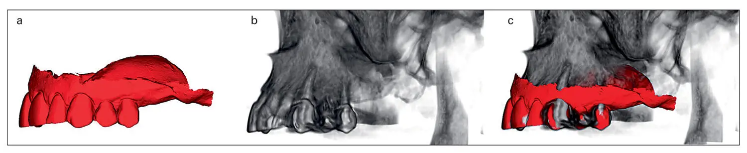
Fig 2.10Using an appropriate implant planning software, the imported 3D surface data from the IOS system (a) can be superimposed onto the 3D model of the jaw obtained by CBCT (b), thereby combining soft and hard tissue information onto the computer screen (c). The software shown here is Smop (Swissmeda, Zurich, Switzerland).
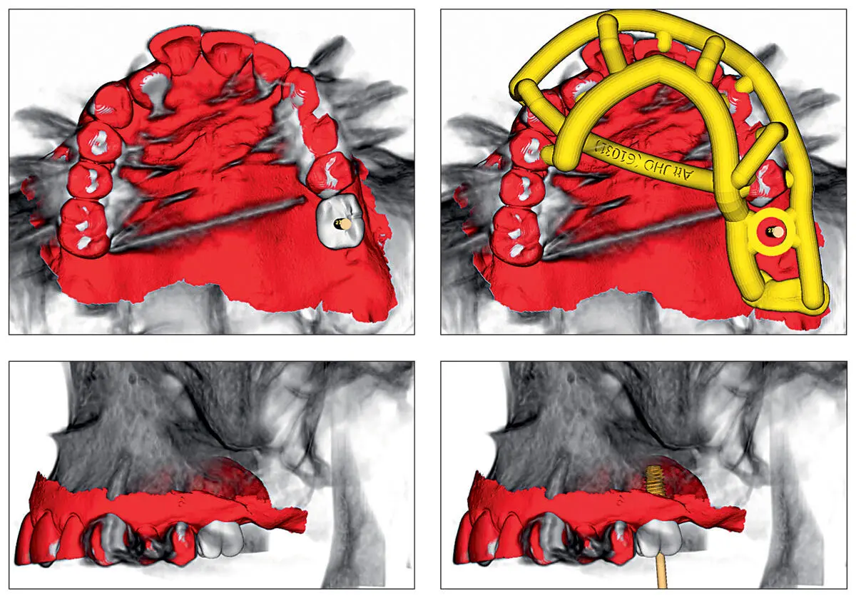
Fig 2.11Consequently, a virtual set-up of the missing tooth can be performed and the implant position can be precisely planned. Accordingly, the software proposes a design of the surgical guide.
Cast Fabrication
Although not provided in all systems, the fabrication of casts based on data acquired by IOS systems is possible. Depending on the IOS system used, two techniques are used for cast fabrication: the additive and the subtractive techniques. For the additive technique, stereolithography (SL) or 3D printing are currently the methods of choice, by which the casts are fabricated by photopolymerized liquid resins, the layers of which are sequentially added and photopolymerized via UV light or visual light. The subtractive technique uses plastic- or resin-based materials in solid form, which are milled by a computer numerical-controlled multiaxis milling machine ( Fig 2.12). The constructed casts can be used either in conventional fabrication of restorations or as a communication tool between the dentist, the patient, and the lab technician. To date, there are few studies available regarding the accuracy of digitally fabricated casts. The subtractive technique shows acceptable accuracy, while the SL technology demonstrates greater accuracy for cast fabrication. 59,60Additionally, it seems that the accuracy is variable across systems. 60
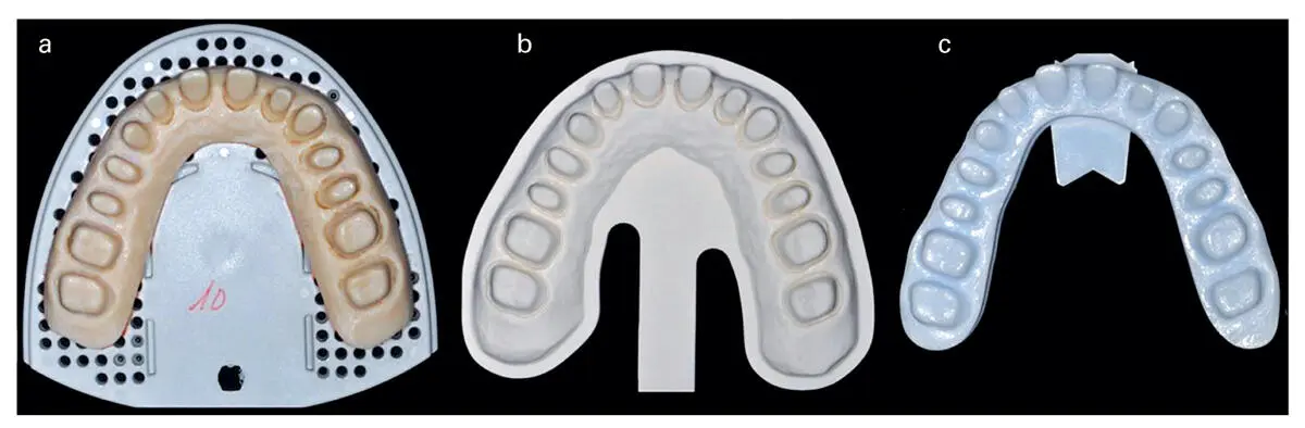
Fig 2.12Casts produced using CAI data from different IOS systems. From left to right: (a) Cerec AC Bluecam (additive manufacturing; stereolithography); (b) iTero (subtractive); and (c) Lava COS (additive).
Implant Capturing Technology Via Photogrammetry
While the digital workflow for the use of IOS systems for CAI of partially edentulous jaws is well established, the use of such systems for edentulous jaws that have received implants remains a difficult task. This is mainly due to the lack of anatomical landmarks to facilitate accurate impressions as well as the lack of knowledge about the accuracy of IOS systems for edentulous jaws with/without implants. In order to solve this issue, the use of photogrammetry to capture the implant positions is proposed. Photogrammetry technology is already in use in the automotive and aerospace industries for quality control of mechanical parts that require very high precision in their manufacture. A representative system of this technique is PIC (PIC dental, Madrid, Spain). The system is comprised of two CCD cameras (PIC camera, PIC dental) ( Fig 2.13), which are designed to accurately determine the position of the implants by means of the identification of flag-shaped abutments screwed onto implants with unique individual coding (PIC abutment, PIC dental; see Figs 2.14and 2.15). The camera has an infrared flash that constantly illuminates the scanned object while eliminating the shadows that occur with ambient light. The PIC camera captures 50 3D photographs for every two PIC abutments. To do this, it automatically takes 10 extraoral pictures per second with an error of less than 10 microns. The registered angles and distances between implants are interrelated and treated as a unit ( Fig 2.16). System software calculates average angles and distances between implants from these photographs, obtaining an accurate relative position of each implant in vector format. The resultant PIC file (PIC dental) contains all the information about implant positions, geometries, connections, healing abutments, and screws that are later required by CAD/CAM software. After capturing of implants, soft tissue registration takes place. This procedure can be carried out using an IOS device or a desktop scanner. The software matches the acquired data of the PIC file and STL of soft tissue registration, yielding a file that contains both implant and soft tissue information. After registration of the opposing arch and maxillomandibular relationship, the data can then be imported into any CAD software to design a future restoration.
Читать дальшеИнтервал:
Закладка:
Похожие книги на «Digital Workflow in Reconstructive Dentistry»
Представляем Вашему вниманию похожие книги на «Digital Workflow in Reconstructive Dentistry» списком для выбора. Мы отобрали схожую по названию и смыслу литературу в надежде предоставить читателям больше вариантов отыскать новые, интересные, ещё непрочитанные произведения.


Обсуждение, отзывы о книге «Digital Workflow in Reconstructive Dentistry» и просто собственные мнения читателей. Оставьте ваши комментарии, напишите, что Вы думаете о произведении, его смысле или главных героях. Укажите что конкретно понравилось, а что нет, и почему Вы так считаете.