Digital Workflow in Reconstructive Dentistry
Здесь есть возможность читать онлайн «Digital Workflow in Reconstructive Dentistry» — ознакомительный отрывок электронной книги совершенно бесплатно, а после прочтения отрывка купить полную версию. В некоторых случаях можно слушать аудио, скачать через торрент в формате fb2 и присутствует краткое содержание. Жанр: unrecognised, на английском языке. Описание произведения, (предисловие) а так же отзывы посетителей доступны на портале библиотеки ЛибКат.
- Название:Digital Workflow in Reconstructive Dentistry
- Автор:
- Жанр:
- Год:неизвестен
- ISBN:нет данных
- Рейтинг книги:4 / 5. Голосов: 1
-
Избранное:Добавить в избранное
- Отзывы:
-
Ваша оценка:
Digital Workflow in Reconstructive Dentistry: краткое содержание, описание и аннотация
Предлагаем к чтению аннотацию, описание, краткое содержание или предисловие (зависит от того, что написал сам автор книги «Digital Workflow in Reconstructive Dentistry»). Если вы не нашли необходимую информацию о книге — напишите в комментариях, мы постараемся отыскать её.
Contributors
Amirah M. R. Alammar • Abdulaziz Alsahaf • Wael Att • Maria Bateli • Jasmin Bernhart • Shaza Bishti • Sarah Blattner • Miha Brezavšček • Sandy Cepa • Nadine Emmanoulidi • Ahmed Fawzy • Manrique Fonseca • Michele Frapporti • Rumpa Ganguly • Yousef Al-Ghamdi • Petra Ch. Gierthmuehlen • Aiste Gintaute • Ulrich Lamott • Christos Lamprinos • Matthias Petsch • Udo Plaster • Aikaterini Ploumaki • Hanna Rauberger • Elisabeth Schwartzkopff • Christian F. Selz • Thamer Al-Sharif • Benedikt Spies • Frank A. Spitznagel • Jörg R. Strub • Michael Swain • Taskin Tuna • Alexander Vuck • Siegbert Witkowski
Digital Workflow in Reconstructive Dentistry — читать онлайн ознакомительный отрывок
Ниже представлен текст книги, разбитый по страницам. Система сохранения места последней прочитанной страницы, позволяет с удобством читать онлайн бесплатно книгу «Digital Workflow in Reconstructive Dentistry», без необходимости каждый раз заново искать на чём Вы остановились. Поставьте закладку, и сможете в любой момент перейти на страницу, на которой закончили чтение.
Интервал:
Закладка:
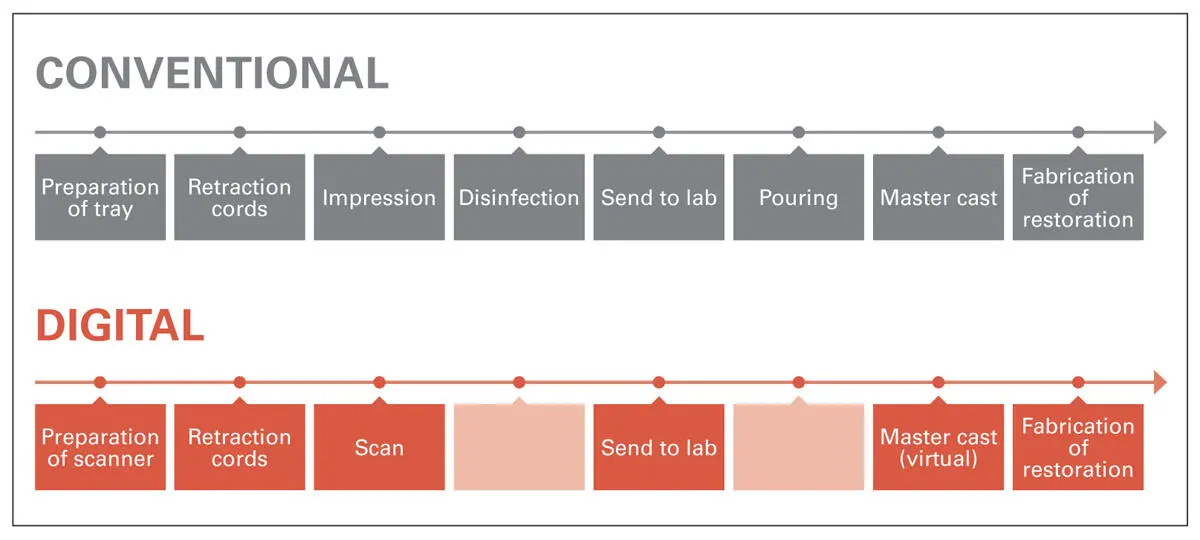
Fig 2.6Comparison between clinical and laboratory steps required for conventional impressions vs. IOS systems.
Requirements of IOS Systems
CAI does not eliminate the problems related to the isolation of subgingival margins. This is especially demanding in the esthetic zone, where the restoration margins have to be hidden. Here, it is obvious that IOS systems require even more preimpression isolation (e.g., placement of retraction cords) of prepared tooth than the conventional impression technique ( Fig 2.7). Conventional impression materials have the ability to flow around the prepared tooth, below the margins into the sulcus, thereby providing a good marginal reading. On the other hand, to achieve an adequate digital impression, the preparation margins must be visible to the naked eye in order to be readable by the IOS system. Otherwise, the application of an intraoral scanner is limited when the gingival tissues cover a deep preparation and block the light beam emitted by the IOS system, preventing the acquisition of an ideal reading to be obtained ( Fig 2.8). Clearly, IOS systems need to be improved in this area. 13
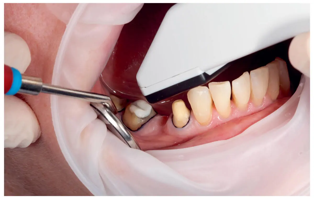
Fig 2.7Clinical procedure for CAI using the iTero IOS system.
Clinical Application of IOS Systems
Digital Impressions Using IOS
Despite their differences, all IOS systems operate under similar principles. For tooth restorations, the dual cord technique is recommended for CAI using IOS systems whenever subgingival preparations are present, so that a direct visualization can be achieved during the scanning procedure ( Fig 2.8). After the intraoral positioning of the camera, the prepared, adjacent, and opposing teeth are scanned. Also, a bite registration must be digitally recorded after the patient is instructed to close into the maximal intercuspal position. Then, the data is processed by the software in order to render a 3D object that represents the scanned structures, which is then displayed on the screen. 9,40The following stage depends on the technology concept of the IOS system used. In-office systems are able to perform not only the digital impression (CAI), but also the design (CAD) of the restoration, manipulating the acquired data with the software provided by the same manufacturer. This process can be accomplished in the dental office exclusively or in the local dental laboratory. Then the digital data of the designed restoration is sent to the milling device of the dental office or the dental laboratory for final production. The majority of IOS systems are designated for CAI, and data must subsequently be uploaded to the manufacturer’s server for further processing. When the manufacturer receives the scan data, a cleaning process is performed to remove the artifacts. Also, a conversion of the data to a compatible file format can be carried out, depending on the system. Therefore, the manufacturers usually charge fees, usually called “data processing fees” or “click fees.” Then, the data is sent to the local lab or the design center where the CAD process takes place. Depending on the particular IOS, the downstream workflow can be categorized into three classes: closed, open, and closed–open systems.
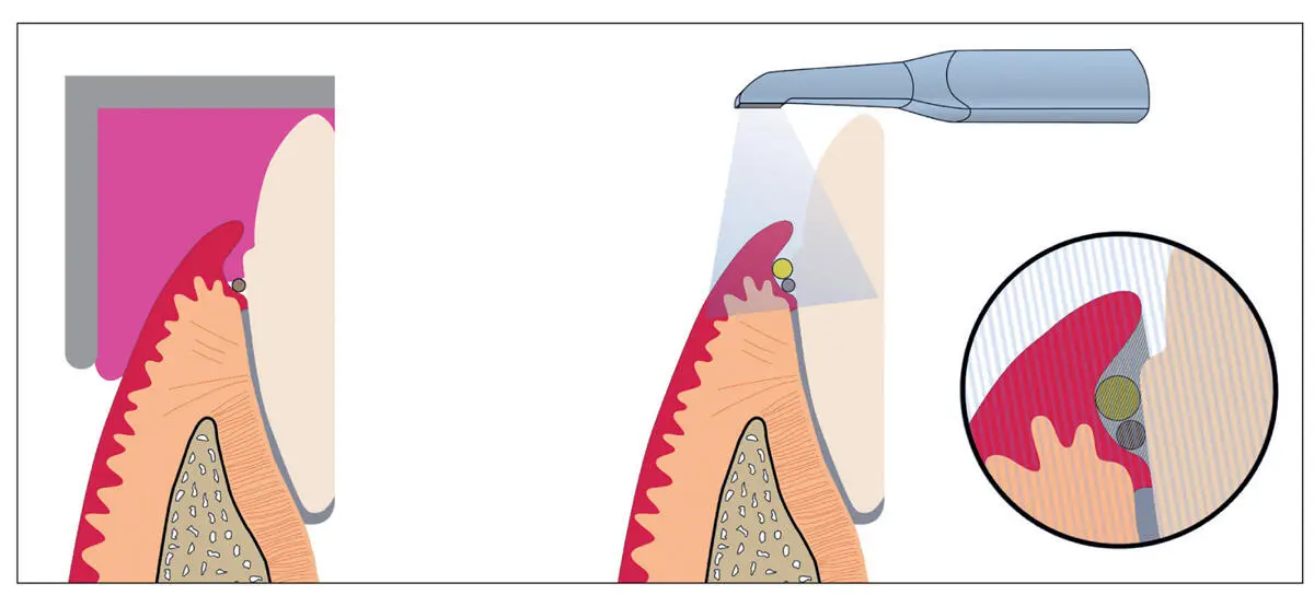
Fig 2.8A representative image of a clinical situation using conventional and digital impression techniques (from left to right). When using IOS, the need for soft tissue retraction around an abutment is of great importance, to allow the light beam emitted by the IOS system to read the preparation margins without limitations.
For closed systems, the same manufacturer provides the IOS, the CAD software, and the CAM device. With open systems, the clinician can choose the preferred CAD software and CAM process. In this case, the scan data must be converted into the Standard Tessellation Language (STL) file format. An STL file describes the surface geometry of a 3D object, ignoring other specifications (e.g., texture, color). This type of file format is universal and supported by most CAD software; however, is not read in the same way across CAD platforms. Therefore, exact information about the CAD operating system is required by the IOS manufacturer to accomplish software-compatible STL format conversion. After the data has been converted, it is sent back to the dental laboratory or the design center where the CAD process takes place and subsequent fabrication of the restoration takes place. For the closed–open systems, the workflow is similar to that of the open systems. However, the dentist or the lab technician requests the option of working with a CAD software package other than that provided by the IOS manufacturer, and the manufacturer converts the data to the STL file format; additional data processing fees are charged.
Implant Digital Impressions Using IOS
For implant-borne restorations, the digital workflow remains fundamentally similar to that for natural abutments. The main difference in such cases is that CAI requires the use of scan bodies. These are devices that can be screw-retained or snapped onto the implants prior to the scanning process and then be scanned by the IOS. They exhibit a specific geometrical surface morphology in order to be identified by the IOS software ( Fig 2.9).
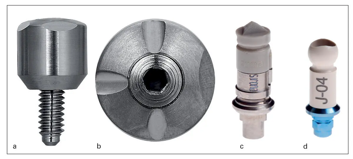
Fig 2.9(a, b) BellaTek Encode Healing Abutment (Zimmer Biomet, Palm Beach Gardens, FL, USA). (c, d) Example of screw-retained scan bodies with different geometries.
The scan bodies allow the scanning device and subsequently the software to accurately determine the 3D position of the dental implant, as well as the associated hard and soft tissues in reference to this position. In other words, the scan bodies are considered as the successors of the traditional implant copings used in such impressions, 41minimizing the steps needed and the potential inaccuracies that can occur all along the conventional process. 42Although the principles of CAI relating to dental implants are similar, the workflow exhibits some differences among the various systems. These differences depend on both the IOS and scan body system. 43After performing the computer-aided impression with the scan body, the scan data must be sent to the manufacturer or to a laboratory equipped with suitable CAD software, where a virtual model with the accurate implant position is created through algorithm alignments. A virtual customized anatomical abutment is designed and can be fabricated. Combining the iTero intraoral scanner (Cadent) with Straumann scan bodies (Institut Straumann, Basel, Switzerland), physical polyurethane casts are milled, followed by assembly of the already designed and fabricated customized abutment and implant analog in the appropriate cast (Insititut Straumann). The cast with the customized abutment is then digitally scanned to enable fabrication of the final restoration. 44For cases in which True Definition Scanner (3M Espe) and BellaTek Encode scan bodies (BellaTek Encode, Zimmer Biomet, Palm Beach Gardens, FL, USA) collaborate, the scan data is simultaneously sent to 3M Espe and Zimmer Biomet. The definitive abutment is designed and milled by Zimmer Biomet, followed by the printing of stereolithographic (SL) models with respect to the final abutment form, by 3M Espe. The abutment and SL models are sent to the lab technician for fabrication of the restoration. 43,45Although this entire process can be accomplished digitally without the SL models, they can provide important information for individualized ceramic veneering. 43BellaTek scan bodies are actually coded healing abutments, which can also be acquired by means of a conventional impression.
Читать дальшеИнтервал:
Закладка:
Похожие книги на «Digital Workflow in Reconstructive Dentistry»
Представляем Вашему вниманию похожие книги на «Digital Workflow in Reconstructive Dentistry» списком для выбора. Мы отобрали схожую по названию и смыслу литературу в надежде предоставить читателям больше вариантов отыскать новые, интересные, ещё непрочитанные произведения.


Обсуждение, отзывы о книге «Digital Workflow in Reconstructive Dentistry» и просто собственные мнения читателей. Оставьте ваши комментарии, напишите, что Вы думаете о произведении, его смысле или главных героях. Укажите что конкретно понравилось, а что нет, и почему Вы так считаете.