Digital Workflow in Reconstructive Dentistry
Здесь есть возможность читать онлайн «Digital Workflow in Reconstructive Dentistry» — ознакомительный отрывок электронной книги совершенно бесплатно, а после прочтения отрывка купить полную версию. В некоторых случаях можно слушать аудио, скачать через торрент в формате fb2 и присутствует краткое содержание. Жанр: unrecognised, на английском языке. Описание произведения, (предисловие) а так же отзывы посетителей доступны на портале библиотеки ЛибКат.
- Название:Digital Workflow in Reconstructive Dentistry
- Автор:
- Жанр:
- Год:неизвестен
- ISBN:нет данных
- Рейтинг книги:4 / 5. Голосов: 1
-
Избранное:Добавить в избранное
- Отзывы:
-
Ваша оценка:
Digital Workflow in Reconstructive Dentistry: краткое содержание, описание и аннотация
Предлагаем к чтению аннотацию, описание, краткое содержание или предисловие (зависит от того, что написал сам автор книги «Digital Workflow in Reconstructive Dentistry»). Если вы не нашли необходимую информацию о книге — напишите в комментариях, мы постараемся отыскать её.
Contributors
Amirah M. R. Alammar • Abdulaziz Alsahaf • Wael Att • Maria Bateli • Jasmin Bernhart • Shaza Bishti • Sarah Blattner • Miha Brezavšček • Sandy Cepa • Nadine Emmanoulidi • Ahmed Fawzy • Manrique Fonseca • Michele Frapporti • Rumpa Ganguly • Yousef Al-Ghamdi • Petra Ch. Gierthmuehlen • Aiste Gintaute • Ulrich Lamott • Christos Lamprinos • Matthias Petsch • Udo Plaster • Aikaterini Ploumaki • Hanna Rauberger • Elisabeth Schwartzkopff • Christian F. Selz • Thamer Al-Sharif • Benedikt Spies • Frank A. Spitznagel • Jörg R. Strub • Michael Swain • Taskin Tuna • Alexander Vuck • Siegbert Witkowski
Digital Workflow in Reconstructive Dentistry — читать онлайн ознакомительный отрывок
Ниже представлен текст книги, разбитый по страницам. Система сохранения места последней прочитанной страницы, позволяет с удобством читать онлайн бесплатно книгу «Digital Workflow in Reconstructive Dentistry», без необходимости каждый раз заново искать на чём Вы остановились. Поставьте закладку, и сможете в любой момент перейти на страницу, на которой закончили чтение.
Интервал:
Закладка:
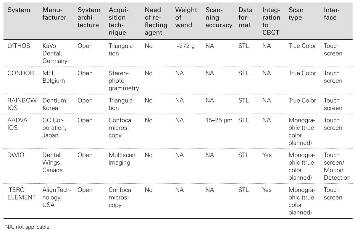
Table 2.1Overview of different features of recently launched intraoral scanner systems (adapted from Zimmerman et al. 19). Features and fees of different systems may vary
Overview of the Digital Workflow
As described earlier in the first chapter of this book, the digital workflow is composed of three components: data acquisition (e.g., computer-aided impression), data manipulation (CAD), and fabrication (CAM) or execution of treatment. From a technological aspect, the CAD/CAM technology can thus be divided in three separate concepts. The first includes a complete chairside CAD/CAM system in the office, where the practitioner can scan the prepared teeth, design the restorations, and manufacture them in the operatory during a single patient visit. The second concept facilitates scanning the prepared teeth and designing the final restoration. Further milling and manufacturing are performed in the laboratory. The latter option focuses only on data acquisition via scanning/digital impression and the practitioner must send the information to a traditional dental laboratory or to a designated CAD/CAM laboratory for the construction of the restoration.
In other words, some IOSs can be used to solely acquire data, while others are intended to acquire the data and also allow the clinician to design the restoration. Obviously, these features relate to the proprietary software of each device and the workflow strategy of the manufacturer.
Intraoral Scanners
The development of IOS systems resulted from the continuous attempt to overcome problems inherent to conventional impressions, such as improper impression tray selection, separation of impression material from the impression tray, and distortion of the impression before pouring. 13,14In fact, more than 50% of conventional impressions are considered as inadequate in terms of reproduction of preparation margins. 15,16Additional motivating factors are the elimination of the need to store the impression for remaking of casts and dies, as well as improvements to the patient’s care and the dentist’s income. 13The process of digital scanning of teeth and/or implants and the surrounding soft and hard structures using specific devices (IOSs) has been described by several terms, such as digital intraoral impression, intraoral scanning, and computer-aided impressioning (CAI).
Today, there are more than 22 major IOS systems available, which all exhibit a relatively similar workflow and largely differ in data capturing and processing techniques. Interestingly, it became usual to find the same hardware product sold under different names, perhaps with a proprietary three-dimensional (3D) scanner software and/or payment plan. 17For example, the visual difference between the Cyrtina IOS (Oratio, the Netherlands), the i/s/can appliance (Goldquadrat, Hanover, Germany), the detection eye (Zirkonzahn, South Tyrol, Italy), the Organical oral scan (R+K, Berlin, Germany), and the 3D progress (MHT, Verona, Italy) can be found only by the logo and perhaps color variant. 17
Data Acquisition Techniques
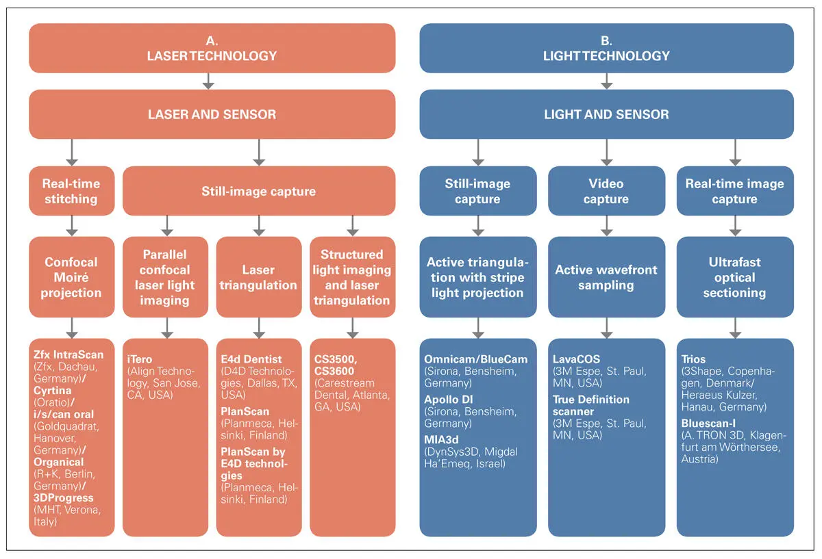
Generally, IOS systems are based on optical scanning techniques. These techniques implement either visible light or an amplified light beam (laser) for object illumination or utilize so-called field sampling, which is then captured and digitized via digital sensors ( Table 2.2).
Table 2.2Overview of various capturing techniques implemented in intraoral scanner systems
Laser Beam-based IOS Systems
Regarding data acquisition technology, laser beam-based IOS systems use either still image (e.g., E4D Dentist, iTero, 3D Progress) or continuous image (e.g., PlanScan) capturing techniques. These techniques enable the IOS to capture a series of images at various angles and positions. 3D rendering of the object in real time follows assembly of the captured images ( Fig 2.3). Depending on the IOS system, the rendered 3D virtual models are either mono- or multichromatic. Although they still do not represent real shades, the so-called true color models facilitate the advantage of simply differentiating between hard and soft tissues. Another main characteristic of laser beam-based IOS systems is that there is no need to use a reflecting agent (except for the E4D Dentist, in cases of presence of a very translucent enamel on the cavosurface or of a metallic restoration on an adjacent tooth). The two main methods implemented in the laser beam-based IOS systems are the parallel confocal imaging technique and the laser triangulation imaging technique.
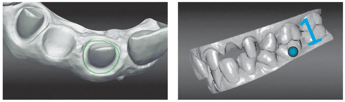
Fig 2.3Rendered 3D data from an intraoral scanner (Zfx, Dachau, Germany).
Parallel Confocal Imaging Technique
The parallel confocal imaging technique is derived from the field of microscopy. In this imaging technique, parallel laser beams are sent through the IOS system’s scanning wand to hit the object that is to be scanned. The laser beams that hit the target at a specific focal length bounce off and return through a small pinhole, strike the laser sensor, and are subsequently converted to a digital image. A representative system implementing this technique is the iTero (Cadent, Carlstadt, NJ, USA). Around 100,000 parallel red laser light beams are projected by the scanner at 300 different focal depths spaced approximately 50 μm apart. This way, a field 14 mm × 18 mm is sampled within one-third of a second and the data is digitized afterwards. 9,18This spacing allows for an approximate scan depth of between 13 and 15 mm. In total, the system captures approximately 3.5 million data points for each arch being scanned. 18The successor of this system was introduced at the International Dental Show (IDS) 2015 and is called the iTero Element (Align Technology, San Jose, CA, USA). The new version of iTero retains the same working principle, while exhibiting enhanced acquisition capabilities, capturing 6,000 frames per second compared to the 800 frames per seconds by its predecessor. 19A similar technique is the confocal microscope recognition with Moiré effect, which is used by some IOS systems (e.g., Zfx/Organical Scan Oral/Cyrtina/3D Progress) ( Fig 2.4).
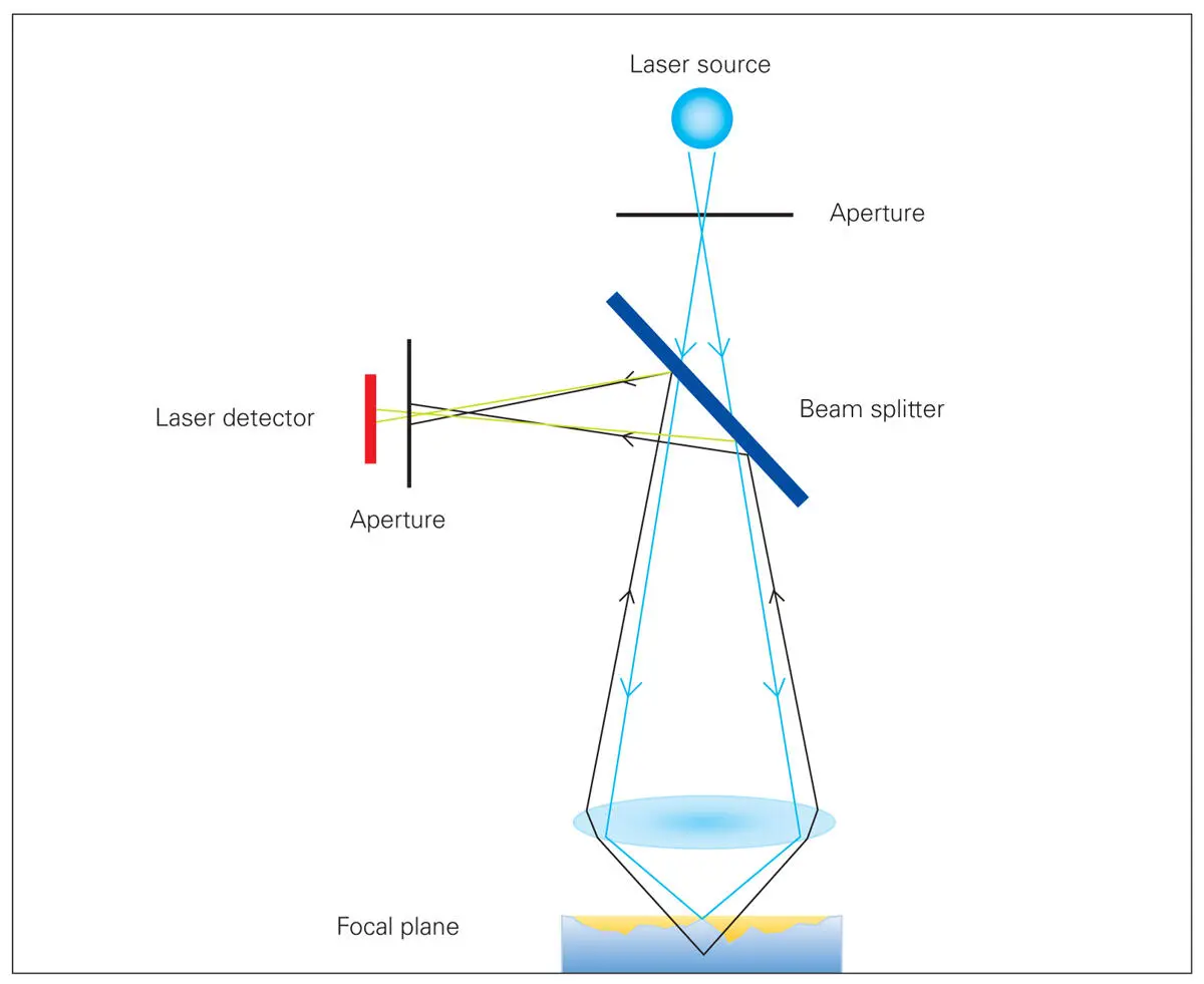
Fig 2.4A representative image of a confocal microscope (3D Progress, MHT, Verona, Italy/ Zfx, Dachau, Germany).
Laser Triangulation Imaging Technique
In this technique, the scanner utilizes a red laser beam and micromirrors that oscillate at 20,000 cycles per second to capture a series of still images from multiple angles around the object in order to generate a 3D model. 4,9,20This technology is similar to the triangulation technique implemented in laser beam-based IOS systems. However, the triangulation technique implemented in light beam-based IOS systems requires only a single orientation of the camera in order to be able to capture all the details of the target area from this single image. 21,22Representative IOS systems that utilize this technique are the E4D system (D4D Technologies LLC, Dallas, TX, USA) and PlanScan (Planmeca, Helsinki, Finland). However, the latter utilizes a blue laser rather than the red laser beam implemented by E4D.
Structured Light Imaging and Laser Triangulation Technique
Читать дальшеИнтервал:
Закладка:
Похожие книги на «Digital Workflow in Reconstructive Dentistry»
Представляем Вашему вниманию похожие книги на «Digital Workflow in Reconstructive Dentistry» списком для выбора. Мы отобрали схожую по названию и смыслу литературу в надежде предоставить читателям больше вариантов отыскать новые, интересные, ещё непрочитанные произведения.


Обсуждение, отзывы о книге «Digital Workflow in Reconstructive Dentistry» и просто собственные мнения читателей. Оставьте ваши комментарии, напишите, что Вы думаете о произведении, его смысле или главных героях. Укажите что конкретно понравилось, а что нет, и почему Вы так считаете.