Industrial Carbon and Graphite Materials
Здесь есть возможность читать онлайн «Industrial Carbon and Graphite Materials» — ознакомительный отрывок электронной книги совершенно бесплатно, а после прочтения отрывка купить полную версию. В некоторых случаях можно слушать аудио, скачать через торрент в формате fb2 и присутствует краткое содержание. Жанр: unrecognised, на английском языке. Описание произведения, (предисловие) а так же отзывы посетителей доступны на портале библиотеки ЛибКат.

- Название:Industrial Carbon and Graphite Materials
- Автор:
- Жанр:
- Год:неизвестен
- ISBN:нет данных
- Рейтинг книги:3 / 5. Голосов: 1
-
Избранное:Добавить в избранное
- Отзывы:
-
Ваша оценка:
Industrial Carbon and Graphite Materials: краткое содержание, описание и аннотация
Предлагаем к чтению аннотацию, описание, краткое содержание или предисловие (зависит от того, что написал сам автор книги «Industrial Carbon and Graphite Materials»). Если вы не нашли необходимую информацию о книге — напишите в комментариях, мы постараемся отыскать её.
Industrial Carbon and Graphite Materials — читать онлайн ознакомительный отрывок
Ниже представлен текст книги, разбитый по страницам. Система сохранения места последней прочитанной страницы, позволяет с удобством читать онлайн бесплатно книгу «Industrial Carbon and Graphite Materials», без необходимости каждый раз заново искать на чём Вы остановились. Поставьте закладку, и сможете в любой момент перейти на страницу, на которой закончили чтение.
Интервал:
Закладка:
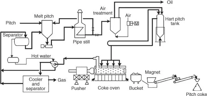
Figure 6.1.3.1 Process flow of Koppers process.
Table 6.1.3.2 Dimension and operational capacity of typical Koppers coke oven.
| Major dimension | Operational capacity per chamber | ||
|---|---|---|---|
| Height (mm) | 3000 | Amount of hard pitch charged (t/chamber) | 9.1 |
| Length (mm) | 11 800 | Process time (hr) | 18 |
| Width (mm) | 450 | Handling capacity of hard pitch (t/day) | 12.2 |
| Production volume of PC (t/day) | 9.2 |
Medium pitch (softening point: approximately 70 °C) or hard pitch (softening point: approximately 150 °C) obtained by injecting air into the medium pitch and large in the residual carbon ratio is used as a raw material. When medium pitch is used, the process for adjusting the hardness in hard pitch is omitted. Pitch is charged into a molten tank (approximately 300 °C) heated in a tubular furnace and then into the hardening vessel, in which air is injected to form hard pitch (yield: approximately 85%) followed by charging it into a circulation tank. Hard pitch in the circulation tank is circulated through a pipeline configured on the surface of the oven in the chamber. A plurality of inlets for charging pitch is configured on the ceiling of the carbonization chamber, and the pitch is charged into the carbonization chamber heated to approximately 1000 °C by opening the valve provided on the circulation pipe directly lying on it. Carbonization of pitch is completed after approximately 20 hours. After completion of carbonization, lids at both ends of the oven in the carbonization chamber are detached to push red hot coke out of the oven with a pusher machine into the quench car through the coke guide car. After the red hot coke is quenched using a water spraying system, a big block of coke is crushed to yield a product. A yield of the PC from medium pitch is around approximately 60%.
6.1.3.3.1.2 Delayed Coker and Calciner
Figure 6.1.3.2illustrates a flow chart of the delayed coker and calciner (hereinafter abbreviated to as delayer coker) process. Delayed coker is similar to the delayer coker and calciner process for manufacturing petroleum coke and is provided with a coke drum (hereinafter abbreviated to as a drum) and a rotary kiln as major equipment.
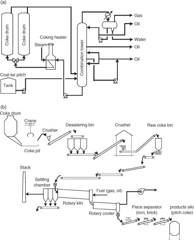
Figure 6.1.3.2 Process flow of delayed coking/calcining process. (a) delayed coking process. (b) calcining process.
6.1.3 Delayed Coking
Delayed coking is operated as follows. SOP (softening point: 20–40 °C) as a raw material is fed into the bottom of the fractional tower and discharged (thermal cracking product) into the bottom of the drum after combining with the heavy fraction separated from the drum, followed by heating it in a heating tubular furnace at the temperature in a range of approximately 450–500 °C to charge into the drum under pressure [5, p. 318 and 2, 3]. At this time, high‐pressure steam is injected into the tubular furnace in order to prevent buildup of coke on the furnace tube. The heavy component in the thermal cracking product charged is carbonized in the drum to form raw coke, and a generated gas and steam are distilled off from the top of the drum together with the oily component not cracked to return to the fractional tower. Fractional distillates are separated as needed in the fractional tower for recovery, and light oil, gases, and water are recovered from the top of the fractional tower. There is a plurality of drums, and as the drum is filled with the solidified raw coke, the thermal cracking product is switched to the second drum. Steam is injected into the drum filled with solidified raw coke to eject the unreacted oily component with steam followed by charging water to cool. After, the top and bottom heads of the full coke drum cooled are removed, and then the solid raw coke is cut from the coke drum with a jet stream of high‐pressure water and transferred into a tank for dewatering.
A typical example of the material balance in coking and the physical properties of coke, oil, and gas is shown in Table 6.1.3.3[1, 7, p. 79]. PC generally differs from petroleum coke as follows:
A yield of the coke relative to the raw material supplied is larger [1, 7, p. 76].
The content of ash and sulfur in raw coke is less and the content of nitrogen is higher [1, 7, p. 76].
Since the aromaticity of the raw material supplied is higher but its reactivity is lower [8, 9, p. 159], coking is performed at higher temperature [1, 7, p. 76].
The aromaticity of oil as a by‐product is high and the content of hydrogen and methane in the gas formed is high [1, 7, p. 76].
The variation of the carbon and hydrogen ratio in different production processes is given in Table 6.1.3.4and Figure 6.1.3.3, respectively. In the case of PC, the C/H ratio indicates that the raw material comprises on average four aromatic rings as in chrysene, but coking of the raw coke increases the number of aromatic rings to exceed 10 as in ovalene, and after calcination the carbon content is almost 99%. The carbon content in the raw material is higher in the case of PC, but the carbon content of raw coke after coking and that in a product after calcination are similar.
As compared with the chamber coking process, the delayed coking process is substantially improved as follows:
Environmental pollution
Table 6.1.3.3 Production of PC by the delayed coking process.
| Material balance and properties of products. | |
|---|---|
| Typical delayed coking yield | wt% of charge |
| Product gas | 3.0 |
| Light oil | 10.7 |
| Heavy oil | 25.4 |
| Coke | 60.9 |
| Total | 100.0 |
| Average properties of products | |
|---|---|
| Product gas | |
| vol% | |
| H2 | 48.2 |
| N2 | Trace |
| CO | 1.0 |
| CO2 | Trace |
| CH4 | 44.9 |
| C2H4 | Trace |
| C2H6 | 5.9 |
| Light oil | ||
|---|---|---|
| Specific gravity | 1.018 | |
| Naphthalene content (wt%) | 32.5 | |
| Distillation (°C) | IBP | 180 |
| 10 | 205 | |
| 50 | 235 | |
| 70 | 247 | |
| 90 | 275 | |
| EP | 310 |
| Heavy oil | ||
|---|---|---|
| Specific gravity | 1.085 | |
| Conradson carbon (wt%) | 0.30 | |
| Distillation (°C) | IBP | 256 |
| 10 | 293 | |
| 50 | 324 | |
| 70 | 338 | |
| 90 | 367 | |
| EP | 400 |
| Coke | |
|---|---|
| Apparent density (lb./cu.ft.) | 61–69 |
| Volatile combustible matter (wt%) | 7.5–9.5 |
Table 6.1.3.4 Variation of the carbon and hydrogen ratio in production steps of pitch coke.
| C (wt%) | H (wt%) | C/H (atomic ratio) | References | |
|---|---|---|---|---|
| Feed | 91.6 | 5.1 | 1.50 | [6] |
| Raw coke | 94.6 | 2.8 | 2.82 | [5] |
| Pitch coke | 98.68 | 0.34 | 24.19 | [4] |
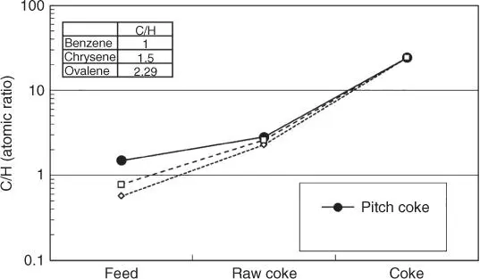
Figure 6.1.3.3 Variation of the carbon and hydrogen ratio in production steps of pitch coke.
Читать дальшеИнтервал:
Закладка:
Похожие книги на «Industrial Carbon and Graphite Materials»
Представляем Вашему вниманию похожие книги на «Industrial Carbon and Graphite Materials» списком для выбора. Мы отобрали схожую по названию и смыслу литературу в надежде предоставить читателям больше вариантов отыскать новые, интересные, ещё непрочитанные произведения.


Обсуждение, отзывы о книге «Industrial Carbon and Graphite Materials» и просто собственные мнения читателей. Оставьте ваши комментарии, напишите, что Вы думаете о произведении, его смысле или главных героях. Укажите что конкретно понравилось, а что нет, и почему Вы так считаете.