Peter D. Minns - Digital System Design using FSMs
Здесь есть возможность читать онлайн «Peter D. Minns - Digital System Design using FSMs» — ознакомительный отрывок электронной книги совершенно бесплатно, а после прочтения отрывка купить полную версию. В некоторых случаях можно слушать аудио, скачать через торрент в формате fb2 и присутствует краткое содержание. Жанр: unrecognised, на английском языке. Описание произведения, (предисловие) а так же отзывы посетителей доступны на портале библиотеки ЛибКат.
- Название:Digital System Design using FSMs
- Автор:
- Жанр:
- Год:неизвестен
- ISBN:нет данных
- Рейтинг книги:5 / 5. Голосов: 1
-
Избранное:Добавить в избранное
- Отзывы:
-
Ваша оценка:
Digital System Design using FSMs: краткое содержание, описание и аннотация
Предлагаем к чтению аннотацию, описание, краткое содержание или предисловие (зависит от того, что написал сам автор книги «Digital System Design using FSMs»). Если вы не нашли необходимую информацию о книге — напишите в комментариях, мы постараемся отыскать её.
Digital System Design using FSMs — читать онлайн ознакомительный отрывок
Ниже представлен текст книги, разбитый по страницам. Система сохранения места последней прочитанной страницы, позволяет с удобством читать онлайн бесплатно книгу «Digital System Design using FSMs», без необходимости каждый раз заново искать на чём Вы остановились. Поставьте закладку, и сможете в любой момент перейти на страницу, на которой закончили чтение.
Интервал:
Закладка:
Note the feed forward paths between the outside world inputs and the input to the output decoder.
The figure shows that the FSM has a number of inputs that connect to the next state decoder(combinational) logic. The Q outputs of the memory element flip‐flops connect to the output decoderlogic, which in turn connects to the outside world outputs via the output decoder.
The flip‐flop outputs are used as next stateinputs to the next state decoder, and it is these that determine the next state that the FSM will move to. Once the FSM has moved to this next state, its flip‐flops acquire a new present stateas dictated by the next state decoder.
Note that some of the outside world inputsconnect directlyto the output decoderlogic. This is the main feature of the Mealytype of FSM. This affects the outputs of the FSM.
Please turn to Frame 1.5 .
Frame 1.5
Another architectural form for an FSM is the MooreFSM, as shown in Figure 1.4.
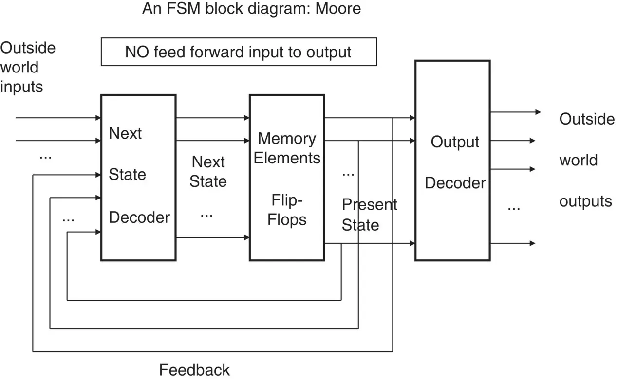
Figure 1.4 Block diagram of a Moore state machine structure.
This FSM differs from the MealyFSM in that it does not have the feed forward paths.
This type of FSM is very common. Note that the outside world outputsare a function of the flip‐flop outputsonly (unlike the Mealy FSMarchitecture where the outside world outputsare a function of flip‐flop outputsand some outside world inputs).
We will be using both Moore and Mealy FSMin our designs.
Please turn to Frame 1.6 .
Frame 1.6
Complete the following:
A Moore FSM differs to that of a Mealy FSM in that it has…
This means that the Moore FSM outputs depend on…
Whilst the Mealy FSM outputs can depend upon…
If you cannot complete the above sentences, go back and read Frame 1.4and Frame 1.5.
When you have completed these questions, please go to Frame 1.7 .
Frame 1.7
If we look at the Moore FSM architecture again and remove all of the outside world inputsapart from the clock, and we also remove the output decoding logic, we are left with a very familiar architecture. This is shown in Figure 1.5.
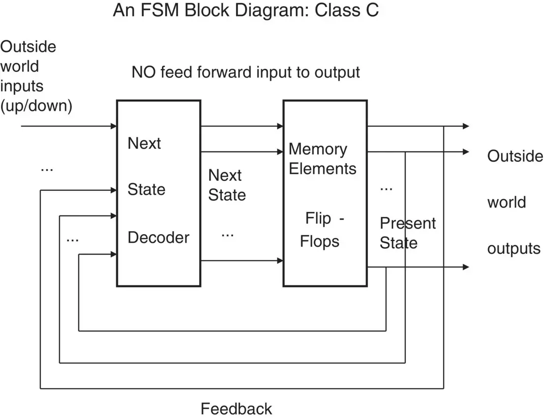
Figure 1.5 Block diagram of a Class C state machine structure.
This architecture is in fact the synchronous counter the reader may have already seen in previous studies. Note that an up/downcounter would have the additional outside world input ‘up/down’, which would be used to control the direction of counting.
The flip‐flop outputs in this architecture are used to connect directly to the outside world.
Please move on to Frame 1.8 .
Frame 1.8
Historically, two types of state diagrams have evolved, one for the design of the MealyFSM the other for the design of the MooreFSM. The two are known as ‘Mealy state diagrams’ and ‘Moore state diagrams’.
These days we use a more general type of state diagram, which can be used to design both the Mealyand Mooretype of FSM. This is the type of state diagram we use throughout this book. As you will learn, it allows you to build a lot of ideas into the FSM diagram.
Figure 1.6shows each state of the FSM and the transitions to and from that state to other states.
The states are usually drawn as circles(but some people like to use a square box).
The transitionsbetween states are shown as an arrowed lineconnected between the states.
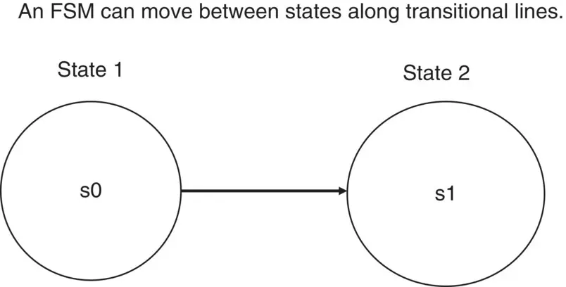
Figure 1.6 Transition between states.
In addition to the transitional line between states, there is an inputsignal name.
The right‐angled lines _| represent the clock input (in this case a rising edge 0 to 1 ) (Figure 1.7 ).
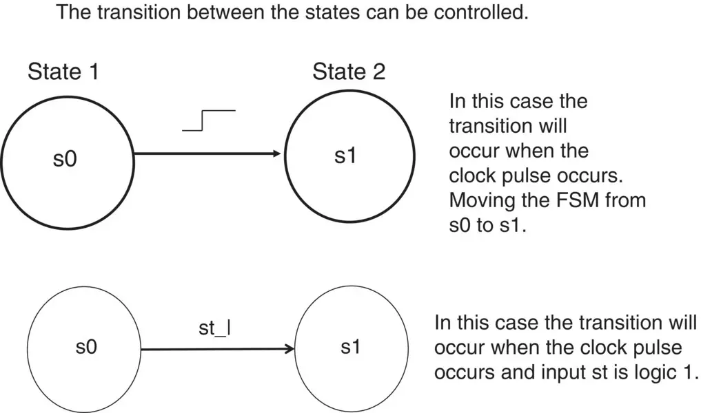
Figure 1.7Transition with and without outside world inputs.
In Figure 1.7, the transition between states s0 and s1 will occur at the clock pulse in the upper state diagram, while in the lower state diagram it will onlyoccur if the outside world input set to 1‘st = 1’ anda ‘0 to 1’ transition occurs on the clock input.
What changes would be needed to Figure 1.7 to make the transition between s0 and s1 occur when input st = 0?
Turn to Frame 1.9 after you have attempted this question.
Frame 1.9
The answer is shown in Figure 1.8.
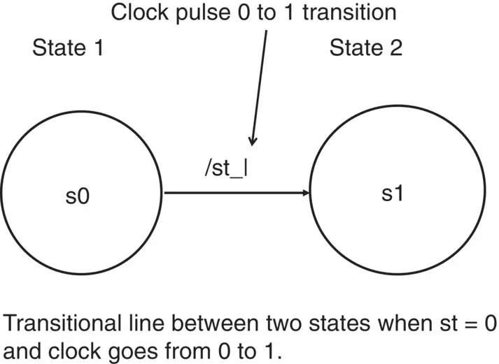
Figure 1.8 Outside world input between states.
Since in this case the outside world input ‘st’ must be equal to zero (denoted by the inverting bar to the left of the input st (as in /st).
That is / means notso /st means not st, i.e. when st = 0, then /st = 1.
Note that outside world inputs always lie along the transitional lines. Also, the reader could be using ‘·’ as well as ‘*’ for ‘AND’. Also, ‘+’ for ‘OR’ in Boolean equations; however, in most cases ‘.’ will be used rather than ‘*’. In some cases no symbol will be used for ‘AND’, as in ‘AB’ to mean ‘A·B’.
The state diagram must also show how the ‘outside world outputs’ are affected. This is achieved by placing the outside world outputs either:
inside the state circle (or square); or
alongside the state circle (or square).
Figure 1.9shows the outside world outputs P and Q inside the state circles. In this particular case, P is logic 1 in state s0, and changes to logic 0 when the FSM moves to state s1. Output Q does not change in the above transaction, remaining at logic 0 in both states.
Draw a block diagram showing inputs and outputs for the state diagram.
Then turn to Frame 1.10 .
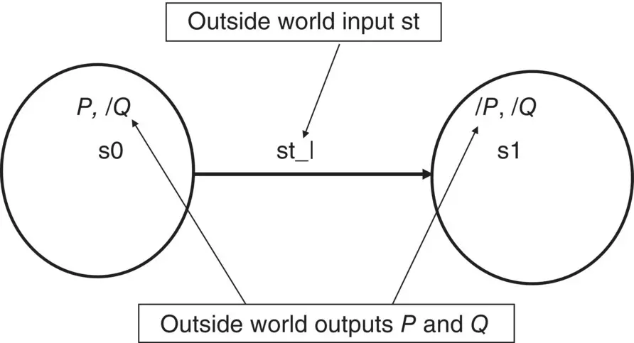
Figure 1.9 Placement of outside world outputs.
Frame 1.10
The block diagram will look like that shown in Figure 1.10.
Читать дальшеИнтервал:
Закладка:
Похожие книги на «Digital System Design using FSMs»
Представляем Вашему вниманию похожие книги на «Digital System Design using FSMs» списком для выбора. Мы отобрали схожую по названию и смыслу литературу в надежде предоставить читателям больше вариантов отыскать новые, интересные, ещё непрочитанные произведения.


Обсуждение, отзывы о книге «Digital System Design using FSMs» и просто собственные мнения читателей. Оставьте ваши комментарии, напишите, что Вы думаете о произведении, его смысле или главных героях. Укажите что конкретно понравилось, а что нет, и почему Вы так считаете.