Mohamed N. Rahaman - Materials for Biomedical Engineering
Здесь есть возможность читать онлайн «Mohamed N. Rahaman - Materials for Biomedical Engineering» — ознакомительный отрывок электронной книги совершенно бесплатно, а после прочтения отрывка купить полную версию. В некоторых случаях можно слушать аудио, скачать через торрент в формате fb2 и присутствует краткое содержание. Жанр: unrecognised, на английском языке. Описание произведения, (предисловие) а так же отзывы посетителей доступны на портале библиотеки ЛибКат.
- Название:Materials for Biomedical Engineering
- Автор:
- Жанр:
- Год:неизвестен
- ISBN:нет данных
- Рейтинг книги:4 / 5. Голосов: 1
-
Избранное:Добавить в избранное
- Отзывы:
-
Ваша оценка:
Materials for Biomedical Engineering: краткое содержание, описание и аннотация
Предлагаем к чтению аннотацию, описание, краткое содержание или предисловие (зависит от того, что написал сам автор книги «Materials for Biomedical Engineering»). Если вы не нашли необходимую информацию о книге — напишите в комментариях, мы постараемся отыскать её.
A comprehensive yet accessible introductory textbook designed for one-semester courses in biomaterials Materials for Biomedical Engineering: Fundamentals and Applications
Materials for Biomedical Engineering: Fundamentals and Applications
Materials for Biomedical Engineering — читать онлайн ознакомительный отрывок
Ниже представлен текст книги, разбитый по страницам. Система сохранения места последней прочитанной страницы, позволяет с удобством читать онлайн бесплатно книгу «Materials for Biomedical Engineering», без необходимости каждый раз заново искать на чём Вы остановились. Поставьте закладку, и сможете в любой момент перейти на страницу, на которой закончили чтение.
Интервал:
Закладка:
Fatigue occurs by a process of slow crack growth under cyclic stresses that are often well below the strength of the material. Cracks formed during cyclic loading or accidentally present in the original material can grow slowly and, when they have propagated sufficiently far, failure occurs, often in a brittle manner, at stresses well below the strength of the material ( Figure 4.11).
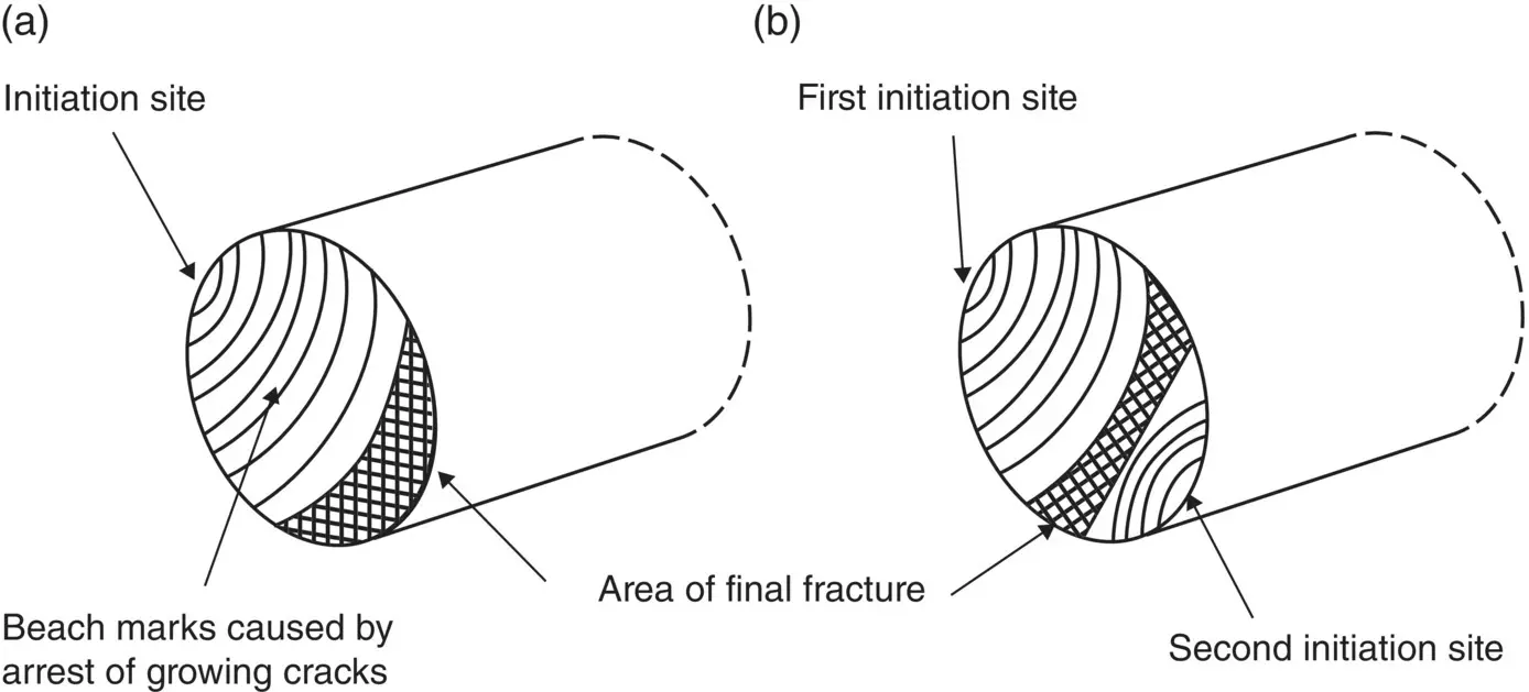
Figure 4.11 Schematic representation of the fracture surface of a ductile metal after fatigue failure in one‐way bending (a) and two‐way bending (b).
Fatigue behavior is commonly studied by subjecting specimens to cyclic loads often sinusoidal in nature, in the requisite loading mode such as tension, compression or bending. Specimens, commonly of a geometry similar to those used to measure the strength of the material ( Section 4.2.1), are loaded for the requisite number of cycles of until they fail.
4.2.8 Hardness
Hardness provides a measure of the resistance of a material to penetration by a sharp object. Loading a material with a sharp indenter results in the creation of a permanent irreversible impression that is indicative of plastic deformation ( Figure 4.12). This occurs even for brittle materials such as ceramics because the stresses due to a sharp indenter are sufficiently high to cause local plastic deformation. The hardness H is determined from the equation
(4.29) 
where, F is the applied load (force) and A is the area of the residual deformation. While indenters of various geometry are available, the Vickers indenter consisting of a square‐shaped pyramid usually made of diamond is often used. The area A used in Eq. (4.29)is the actual area of the residual indent, that is, the area between the four faces of the pyramid and the surface of the solid after the indenter has been removed. Thus, for the Vickers indenter
(4.30) 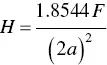
where, 2 a is the length of the diagonal of the indenter ( Figure 4.12). The hardness determined from Eq. (4.30)is called the Vickers hardness. In another measure of hardness, sometimes called the true hardness, the projected area of indent is used in Eq. (4.29), giving
(4.31) 
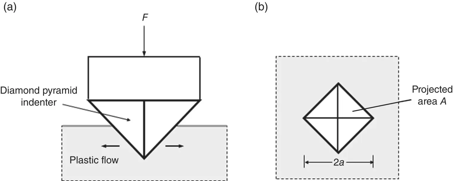
Figure 4.12 Geometry of hardness test using a Vickers indenter consisting of a square‐shaped pyramid. (a) Side view of the indentation test. (b) View of the indent looking directly at the surface of the material.
The true hardness is ~8% higher than the Vickers hardness and, thus, it is useful to state which hardness is being reported.
For some ductile metals, H is related to the yield strength σ yby the equation
(4.32) 
but a correction factor is needed for other metals that become stronger with increasing plastic deformation (a process called work hardening or strain hardening). As seen from Eq. (4.32), measuring the hardness provides a simple and nondestructive test for determining the yield strength of a material. There is no need to make tensile specimens and the indenter is so small that several measurements can be performed on the same material sample without severely damaging it.
Hardness controls the resistance to abrasive wear between the articulating surfaces of two materials. The harder the material, the less prone it is to wear. Wear is particularly important, for example, in implants used for total joint replacement ( Chapter 23). The production of excessive wear particles between the articulating surfaces in these implants, such as between the CoCr ball and ultrahigh molecular weight polyethylene (UHMWPE) liner in a hip implant, leads to a severe foreign body response that invariably causes implant failure ( Chapter 18).
4.3 Effect of Microstructure on Mechanical Properties
The microstructure of a material controls its mechanical properties and other physical properties ( Chapter 3). Microstructural parameters that have a major influence on mechanical properties are
Porosity, the volume fraction of pores in the material, as well as their distribution within the material and their shape
Grain size, relevant to metals and ceramics
Presence of microstructural flaws such as microcracks and pores, often introduced accidentally during fabrication of the material, particularly relevant to brittle materials.
4.3.1 Effect of Porosity
Porosity has a strong effect in reducing the elastic modulus ( Figure 4.13) and the strength of materials. Introduction of porosity into metals and ceramics is a well‐known approach to bring their high strength and elastic modulus closer to those of bone. A variety of equations, theoretical and empirical, has been proposed to account for the effect of porosity on elastic modulus and strength. A popular equation based on a combination of simplicity and accuracy is
(4.33) 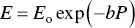
where, E is the Young’s modulus, E ois the Young’s modulus at zero porosity, P is the porosity and b is parameter that depends on the shape and distribution of the pores in the material. Commonly, b is determined empirically from a fit of the experimental data for E versus P . For example, a good fit of Eq. (4.33)to the data shown in Figure 4.13for a titanium alloy is obtained using E o= 80 GPa and b = 4.7. Equation (4.33)often provides a good fit to data for P values up to ~25–40%. For higher porosity, one modification gives
(4.34) 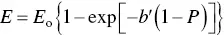
where, b ′ is a parameter determined from fitting the experimental data. Relationships similar in form to Eqs. (4.33)and (4.34)are often used to empirically describe the decrease in strength with porosity.
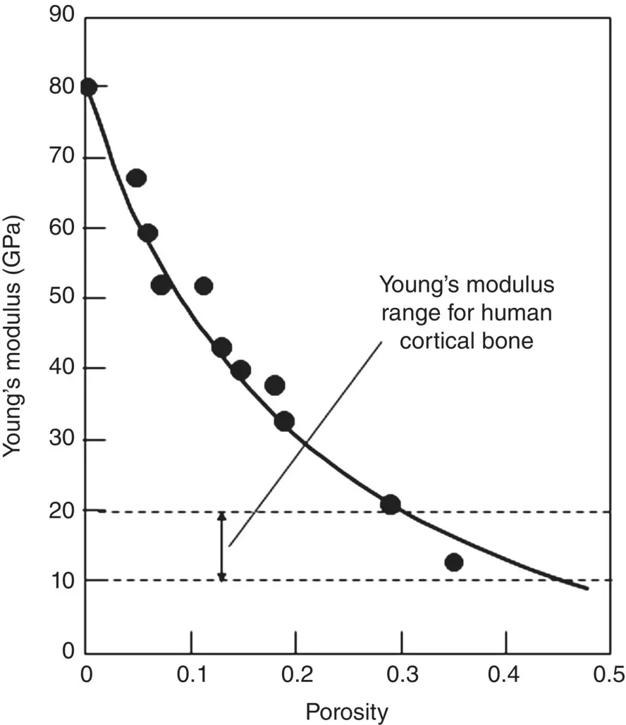
Figure 4.13 Data for the Young’s modulus as a function of porosity for a titanium specimen. The data points are fitted by a smooth curve.
4.3.2 Effect of Grain Size
The yield stress of ductile metals is observed to increase with decreasing grain size ( Figure 4.14), according to the well‐known Hall–Petch equation, given by
(4.35) 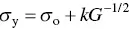
Интервал:
Закладка:
Похожие книги на «Materials for Biomedical Engineering»
Представляем Вашему вниманию похожие книги на «Materials for Biomedical Engineering» списком для выбора. Мы отобрали схожую по названию и смыслу литературу в надежде предоставить читателям больше вариантов отыскать новые, интересные, ещё непрочитанные произведения.


Обсуждение, отзывы о книге «Materials for Biomedical Engineering» и просто собственные мнения читателей. Оставьте ваши комментарии, напишите, что Вы думаете о произведении, его смысле или главных героях. Укажите что конкретно понравилось, а что нет, и почему Вы так считаете.