Iam-Choon Khoo - Liquid Crystals
Здесь есть возможность читать онлайн «Iam-Choon Khoo - Liquid Crystals» — ознакомительный отрывок электронной книги совершенно бесплатно, а после прочтения отрывка купить полную версию. В некоторых случаях можно слушать аудио, скачать через торрент в формате fb2 и присутствует краткое содержание. Жанр: unrecognised, на английском языке. Описание произведения, (предисловие) а так же отзывы посетителей доступны на портале библиотеки ЛибКат.
- Название:Liquid Crystals
- Автор:
- Жанр:
- Год:неизвестен
- ISBN:нет данных
- Рейтинг книги:4 / 5. Голосов: 1
-
Избранное:Добавить в избранное
- Отзывы:
-
Ваша оценка:
Liquid Crystals: краткое содержание, описание и аннотация
Предлагаем к чтению аннотацию, описание, краткое содержание или предисловие (зависит от того, что написал сам автор книги «Liquid Crystals»). Если вы не нашли необходимую информацию о книге — напишите в комментариях, мы постараемся отыскать её.
Liquid Crystals,
Liquid Crystals
Liquid Crystals
Liquid Crystals — читать онлайн ознакомительный отрывок
Ниже представлен текст книги, разбитый по страницам. Система сохранения места последней прочитанной страницы, позволяет с удобством читать онлайн бесплатно книгу «Liquid Crystals», без необходимости каждый раз заново искать на чём Вы остановились. Поставьте закладку, и сможете в любой момент перейти на страницу, на которой закончили чтение.
Интервал:
Закладка:
(3.66) 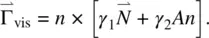
Here  is the rate of change of the director with respect to the immobile background fluid, given by
(3.67) 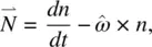
where  is the angular velocity of the liquid. In Eq. (3.66)
  is the velocity gradient tensor defined by Eq. (3.60).
The viscosity coefficients γ 1and γ 2are related to the Leslie coefficient α s by [3]
(3.68a) 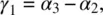
(3.68b) 
Consider the flow configuration depicted in Figure 3.11. Without the magnetic field and setting ϕ = 0, we have
(3.69a) 
(3.69b) 
(3.69c) 
(3.69d) 
(3.69e) 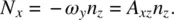
From Eq. (3.66)the viscous torque along the y ‐direction is given by
(3.70) 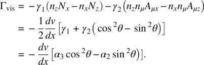
In the steady state, from which the shear torque vanishes, a stable director axis orientation is induced by the flow with an angle θ flowgiven by
(3.71) 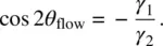
For more complicated flow geometries, the director axis orientation will assume correspondingly complex profiles.
3.6. FIELD‐INDUCED DIRECTOR AXIS REORIENTATION EFFECTS
We now consider the process of director axis reorientation by an external static or low‐frequency field. Optical field effects are discussed in Chapter 6. The following examples will illustrate some of the important relationships among the various torques and dynamical effects discussed in the preceding sections. We will consider the magnetic field as it does not involve complicated local field effects and other electric phenomena (e.g. conduction). The electric field counterparts of the results obtained here for the magnetic field can be simply obtained by the replacement of Δ χ m H 2by Δ εE 2(cf. Eqs. [ 3.26] and [ 3.29]).
3.6.1. Field‐induced Reorientation Without Flow Coupling: Freedericksz Transition
The following example demonstrates how the viscosity coefficient γ 1comes into play in field‐induced reorientational effects. Consider pure twist deformation caused by an externally applied field  on a planar sample as depicted in Figure 3.12. Let θ denote the angle of deformation. The director axis
  is thus given by
  = (cos θ , sin θ , 0). From this and the preceding equations, the free energy ( Eq. 3.4) and elastic torque ( Eq. 3.13) are, respectively,
(3.72a) 
and
(3.72b) 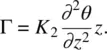
Figure 3.12. Pure twist deformation induced by an external magnetic field H on a planar sample; there is no fluid motion.
The viscous torque is given by
(3.73) 
The torque exerted by the external field  (applied perpendicular to the initial director axis), from Eq. (3.29), becomes
(3.74) 
Hence, the torque balance τ equation gives
(3.75a) 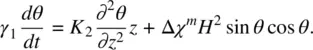
In the equilibrium situation, γ 1 dθ / dt = 0, and Eq. (3.75a)becomes
(3.75b) 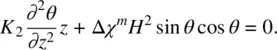
An interesting result from this equation is the so‐called Freedericksz transition [3]. For an applied field strength less than a critical field H F, θ = 0. For H > H F, reorientation occurs. The expression for H Fis given by
(3.76) 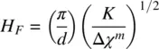
assuming that the reorientation obeys the hard‐boundary (strong anchoring) condition (i.e. θ = 0 at z = 0 and at z = d ). For H just above H F, θ is given approximately by
(3.77a) 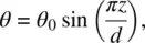
where
(3.77b) 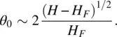
Интервал:
Закладка:
Похожие книги на «Liquid Crystals»
Представляем Вашему вниманию похожие книги на «Liquid Crystals» списком для выбора. Мы отобрали схожую по названию и смыслу литературу в надежде предоставить читателям больше вариантов отыскать новые, интересные, ещё непрочитанные произведения.


Обсуждение, отзывы о книге «Liquid Crystals» и просто собственные мнения читателей. Оставьте ваши комментарии, напишите, что Вы думаете о произведении, его смысле или главных героях. Укажите что конкретно понравилось, а что нет, и почему Вы так считаете.