Ernst Lueder - Liquid Crystal Displays
Здесь есть возможность читать онлайн «Ernst Lueder - Liquid Crystal Displays» — ознакомительный отрывок электронной книги совершенно бесплатно, а после прочтения отрывка купить полную версию. В некоторых случаях можно слушать аудио, скачать через торрент в формате fb2 и присутствует краткое содержание. Жанр: unrecognised, на английском языке. Описание произведения, (предисловие) а так же отзывы посетителей доступны на портале библиотеки ЛибКат.
- Название:Liquid Crystal Displays
- Автор:
- Жанр:
- Год:неизвестен
- ISBN:нет данных
- Рейтинг книги:4 / 5. Голосов: 1
-
Избранное:Добавить в избранное
- Отзывы:
-
Ваша оценка:
Liquid Crystal Displays: краткое содержание, описание и аннотация
Предлагаем к чтению аннотацию, описание, краткое содержание или предисловие (зависит от того, что написал сам автор книги «Liquid Crystal Displays»). Если вы не нашли необходимую информацию о книге — напишите в комментариях, мы постараемся отыскать её.
THE NEW EDITION OF THE GOLD-STANDARD IN TEACHING AND REFERENCING THE FUNDAMENTALS OF LCD TECHNOLOGIES
Liquid Crystal Displays — читать онлайн ознакомительный отрывок
Ниже представлен текст книги, разбитый по страницам. Система сохранения места последней прочитанной страницы, позволяет с удобством читать онлайн бесплатно книгу «Liquid Crystal Displays», без необходимости каждый раз заново искать на чём Вы остановились. Поставьте закладку, и сможете в любой момент перейти на страницу, на которой закончили чтение.
Интервал:
Закладка:
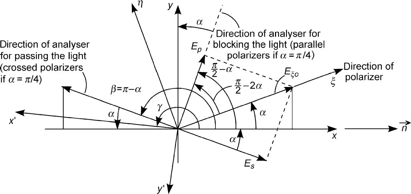
Figure 3.8 Angles of polarizer and analyser for the Fréedericksz cell
At the output of the cell for z = d , where d is the thickness of the cell, the retardation is
(3.57) 
This retardation is associated with a change of phase by δ = π after the wave has propagated the distance d through the cell. The cell operates as a λ /2-plate. Obviously, the retardation is the phase shift measured in parts of λ 0.
For linear polarization with wavelength λ 0corresponding to the angular frequency ω 0of the electric field, the components in Equations (3.42)and (3.43)at z = d are
(3.58) 
(3.59) 
Equations (3.58)and (3.59)reveal the angle β of the linearly polarized light at z = d as
(3.60) 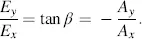
Due to Equations (3.46)and (3.47), we obtain on the other hand for the light at z = 0
(3.61) 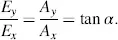
Equations (3.60)and (3.61)indicate
(3.62) 
as shown in Figure 3.8, where all important angles for a Fréedericksz cell are drawn.
The result for a wavelength λ 0at the output z = d of a cell without a voltage applied is linearly polarized light at an angle β = π − а , where α is the angle of the incoming linearly polarized light. If we place the analyser in the direction β = π − α the light can pass representing the normally white mode. The analyser perpendicular to β that is at an angle π/2 − α in Figure 3.8blocks the light representing the normally black mode. We will investigate these two modes in greater detail.
We choose the angle γ for which the x′−y′ plane in Figure 3.8is rotated from the x−y plane as γ = β = π − α. This provides, along with Equations (3.40)and (3.41),
(3.63) 
(3.64) 
or for the electrical field
(3.65) 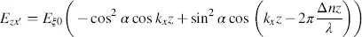
and
(3.66) 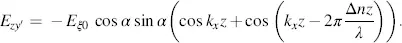
For the wavelength λ = λ 0in Equation (3.57), we obtain at z = d
(3.67) 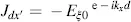
(3.68) 
as expected, since we know already that at z = d light with wavelength λ 0is linearly polarized in the direction β = π − α. For this case, the Jones vectors provide the components of the electrical field as
(3.69) 
(3.70) 
Now we place the analyser perpendicular to the angle β = π − α that is in the direction with angle γ = π /2 − α in Figure 3.8. For this case Jzx ′is identical to − Jzy ′in Equation (3.64)and (3.66)and Jzy ′is identical with Jzx ′in Equations (3.63)and (3.64). Hence, we investigate Equations (3.63)through (3.66)for both cases. The intensity I′x = |Jdx ′ | 2for z = d is, with Equation (3.63),
(3.71) 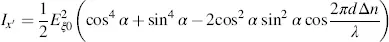
or
(3.72) 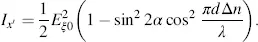
For  , Equation (3.64)yields
(3.73) 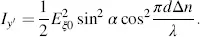
In order to learn how to choose a , we now consider the case of a large enough voltage across the LC cell to fully orient the LC molecules apart from two thin layers on top of the orientation layer, due to Δ ε > 0 in parallel to the electric field. The linearly polarized light coming in at angle a no longer experiences birefringence, as it is only exposed to the refractive index n┴ . It reaches the plane z = d with the phase shift 2π( n┴d / λ ). Its component Ep passing an analyser with the angle (π/2) − α in Figure 3.8is
(3.74) 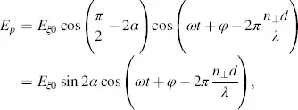
whereas the component Es passing an analyser with the angle π − α in Figure 3.8is
(3.75) 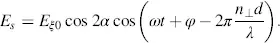
The intensities belonging to Ep and Es are
(3.76) 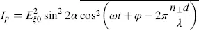
and
(3.77) 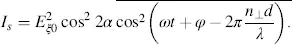
The bar over the cos terms means the average over time needed for calculating the intensity. The maximum of Ip occurs for α = π/4, which (according to Figure 3.8) places the polarizer and analyser in parallel. Is assumes a maximum for α = 0, for which again the polarizer and analyser pertaining to Es are in parallel.
Читать дальшеИнтервал:
Закладка:
Похожие книги на «Liquid Crystal Displays»
Представляем Вашему вниманию похожие книги на «Liquid Crystal Displays» списком для выбора. Мы отобрали схожую по названию и смыслу литературу в надежде предоставить читателям больше вариантов отыскать новые, интересные, ещё непрочитанные произведения.


Обсуждение, отзывы о книге «Liquid Crystal Displays» и просто собственные мнения читателей. Оставьте ваши комментарии, напишите, что Вы думаете о произведении, его смысле или главных героях. Укажите что конкретно понравилось, а что нет, и почему Вы так считаете.