Neil McCartney - Properties for Design of Composite Structures
Здесь есть возможность читать онлайн «Neil McCartney - Properties for Design of Composite Structures» — ознакомительный отрывок электронной книги совершенно бесплатно, а после прочтения отрывка купить полную версию. В некоторых случаях можно слушать аудио, скачать через торрент в формате fb2 и присутствует краткое содержание. Жанр: unrecognised, на английском языке. Описание произведения, (предисловие) а так же отзывы посетителей доступны на портале библиотеки ЛибКат.
- Название:Properties for Design of Composite Structures
- Автор:
- Жанр:
- Год:неизвестен
- ISBN:нет данных
- Рейтинг книги:4 / 5. Голосов: 1
-
Избранное:Добавить в избранное
- Отзывы:
-
Ваша оценка:
Properties for Design of Composite Structures: краткое содержание, описание и аннотация
Предлагаем к чтению аннотацию, описание, краткое содержание или предисловие (зависит от того, что написал сам автор книги «Properties for Design of Composite Structures»). Если вы не нашли необходимую информацию о книге — напишите в комментариях, мы постараемся отыскать её.
A comprehensive guide to analytical methods and source code to predict the behavior of undamaged and damaged composite materials Properties for Design of Composite Structures: Theory and Implementation Using Software
Properties for Design of Composite Structures: Theory and Implementation Using Software
Properties for Design of Composite Structures — читать онлайн ознакомительный отрывок
Ниже представлен текст книги, разбитый по страницам. Система сохранения места последней прочитанной страницы, позволяет с удобством читать онлайн бесплатно книгу «Properties for Design of Composite Structures», без необходимости каждый раз заново искать на чём Вы остановились. Поставьте закладку, и сможете в любой момент перейти на страницу, на которой закончили чтение.
Интервал:
Закладка:
A right-handed second set of local coordinates x′1,x′2andx′3 is obtained by rotating the reference set of coordinates about the x 3-axis by an angle ϕ as shown in Figure 2.1. The rotation is clockwise when viewing along the positive direction of the x 3-axis. The unit vectors in the directions of the x′1,x′2andx′3 axes are denoted by i′1,i′2andi′3, respectively. Rotating about the x 3-axis enables account to be taken of the effects of off-axis plies in laminates, as considered in Chapters 6and 7.
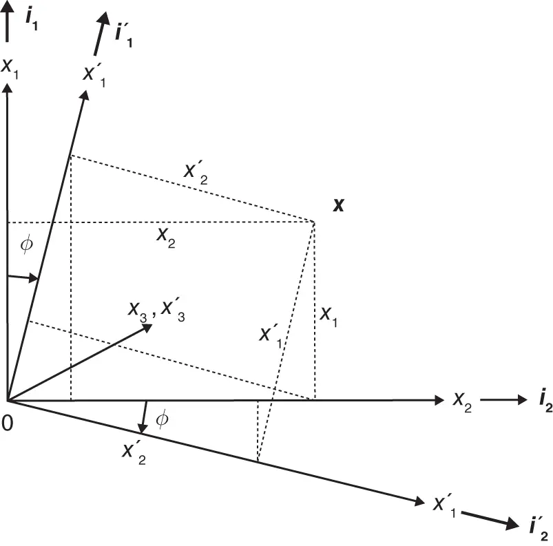
Figure 2.1 Transformation of right-handed Cartesian coordinates.
Any point in space can be represented by the vector x(a first-order tensor) the value of which is wholly independent of the coordinate system that is used to describe its components so that
 (2.171)
It then follows on resolving vectors that
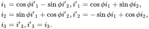 (2.172)
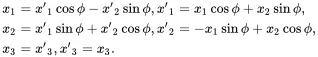
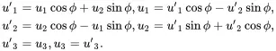
Transformation of a set of Cartesian coordinates (x1,x2,x3) to (x′1,x′2,x′3) by a rotation of the x 1- and x 2-axes about the x 3-axis through an angle ϕ (as shown in Figure 2.1) leads to
 (2.173)
These relationships can be established from the geometry shown in Figure 2.1 on making use of the various constructions shown as dotted lines.
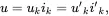
The displacement vector uis a physical quantity that is wholly independent of the coordinate system that is used to describe its components. This vector may be written as (where summation over values 1, 2 and 3 is implied by repeated lowercase suffices)
 (2.174)
where uk and u′k are the displacement components referred to the two coordinate systems being considered. It follows on using ( 2.172) that
 (2.175)
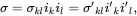
The stress and strain at any point in a material is a dyadic (an array of ordered vector pairs) or second-order tensor whose value is wholly independent of the coordinate system that is used to describe its components. The second-order stress tensor σ may, therefore, be written as (where summation over values 1, 2 and 3 is implied by repeated lower case suffices)
 (2.176)
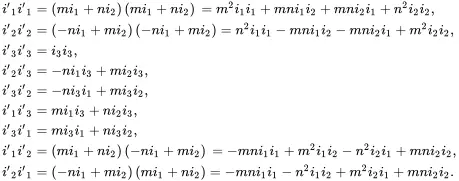
where σkl and σ′kl are the stress components referred to the two coordinate systems being considered. On defining m = cos ϕ and n = sin ϕ , it follows from ( 2.172) that
 (2.177)
Thus, from ( 2.176) and ( 2.177), because σ′12=σ′21, σ′13=σ′31 and σ′23=σ′32
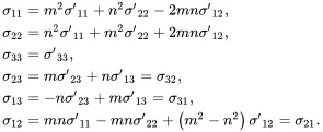 (2.178)
The inverse relationships are obtained by replacing ϕ by −ϕ (i.e. n is replaced by – n ) so that
 (2.179)
The relationships ( 2.178) and ( 2.179) are the standard transformations, arising from tensor theory, for the rotation of stress components about one axis of a right-handed rectangular set of Cartesian coordinates. Identical transformations apply when considering the strain tensor so that
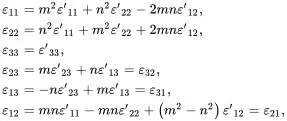 (2.180)
with inverse relations
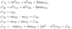 (2.181)
2.17 Transformations of Elastic Constants
On substituting the stress-strain relations ( 2.170) into ( 2.181)
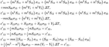 (2.182)
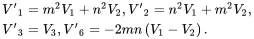
Substitution of ( 2.178) into ( 2.182) leads to the relations
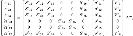 (2.183)
where
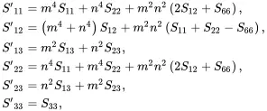 (2.184)
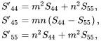 (2.185)
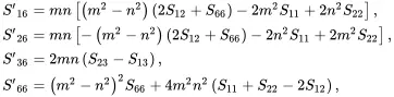 (2.186)
and where
 (2.187)
2.17.1 Transverse Isotropic and Isotropic Solids
When considering unidirectionally reinforced fibre composites, as will be the case in Chapter 4, the effective composite properties are often assumed to be isotropic in the plane that is normal to the fibre direction taken here to be the x 3-direction as coordinate rotations considered previously have been about the x 3-axis. It is now assumed that S11=S22, S44=S55 and S13=S23. As m2 + n2 = 1 and

it then follows from ( 2.184)–( 2.186) that
 (2.188)
It should be noted that the factor S66−2S11+2S12 appears repeatedly in these relations. When this factor is zero so that
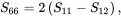 (2.189)
Интервал:
Закладка:
Похожие книги на «Properties for Design of Composite Structures»
Представляем Вашему вниманию похожие книги на «Properties for Design of Composite Structures» списком для выбора. Мы отобрали схожую по названию и смыслу литературу в надежде предоставить читателям больше вариантов отыскать новые, интересные, ещё непрочитанные произведения.


Обсуждение, отзывы о книге «Properties for Design of Composite Structures» и просто собственные мнения читателей. Оставьте ваши комментарии, напишите, что Вы думаете о произведении, его смысле или главных героях. Укажите что конкретно понравилось, а что нет, и почему Вы так считаете.