Neil McCartney - Properties for Design of Composite Structures
Здесь есть возможность читать онлайн «Neil McCartney - Properties for Design of Composite Structures» — ознакомительный отрывок электронной книги совершенно бесплатно, а после прочтения отрывка купить полную версию. В некоторых случаях можно слушать аудио, скачать через торрент в формате fb2 и присутствует краткое содержание. Жанр: unrecognised, на английском языке. Описание произведения, (предисловие) а так же отзывы посетителей доступны на портале библиотеки ЛибКат.
- Название:Properties for Design of Composite Structures
- Автор:
- Жанр:
- Год:неизвестен
- ISBN:нет данных
- Рейтинг книги:4 / 5. Голосов: 1
-
Избранное:Добавить в избранное
- Отзывы:
-
Ваша оценка:
Properties for Design of Composite Structures: краткое содержание, описание и аннотация
Предлагаем к чтению аннотацию, описание, краткое содержание или предисловие (зависит от того, что написал сам автор книги «Properties for Design of Composite Structures»). Если вы не нашли необходимую информацию о книге — напишите в комментариях, мы постараемся отыскать её.
A comprehensive guide to analytical methods and source code to predict the behavior of undamaged and damaged composite materials Properties for Design of Composite Structures: Theory and Implementation Using Software
Properties for Design of Composite Structures: Theory and Implementation Using Software
Properties for Design of Composite Structures — читать онлайн ознакомительный отрывок
Ниже представлен текст книги, разбитый по страницам. Система сохранения места последней прочитанной страницы, позволяет с удобством читать онлайн бесплатно книгу «Properties for Design of Composite Structures», без необходимости каждый раз заново искать на чём Вы остановились. Поставьте закладку, и сможете в любой момент перейти на страницу, на которой закончили чтение.
Интервал:
Закладка:
As the shear stresses σ13 and σ23 are everywhere zero, it follows from ( 2.143), ( 2.209) and ( 2.211) that
 (2.227)
Integration then yields
 (2.228)
These relations must be consistent with ( 2.226) so that
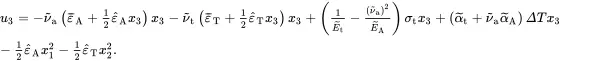 (2.229)
where the displacement component has been selected to be zero at the origin.
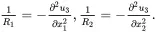
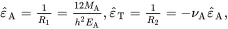
The through-thickness displacement of the top surface of the beam, at x3=0, can be defined in terms of two lengths, R 1and R 2, which are the radii of curvature of this surface in the x 1– x 3plane and the x 2– x 3plane, respectively. The exact relationships are given by the well-known formulae
 (2.230)
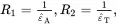
For small deflections
 (2.231)
Thus, it follows from ( 2.229) that
 (2.232)
providing a useful physical interpretation of the strain parameters ε^A and ε^T.
The final requirement is to determine the loading state that is consistent with the various strain parameter values. It is assumed that stresses within the beam can arise from an applied in-plane loading that is equivalent to an applied axial force FA and a transverse force FT acting in the mid-plane between the upper and lower surfaces of the beam, and an axial applied bending moment per unit area of cross section MA and a transverse applied bending moment per unit area of cross section MT . From mechanical equilibrium
 (2.233)
 (2.234)
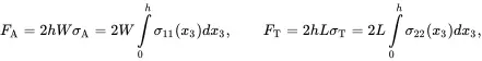
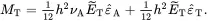
where σA and σT are the effective axial and transverse applied stresses. On substituting ( 2.220) and ( 2.221) into ( 2.233), the following effective axial and transverse stresses are obtained
 (2.235)
 (2.236)
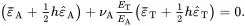
The relations ( 2.234) are now expressed in the form
 (2.237)
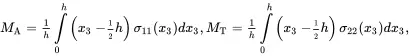
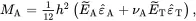
On substituting ( 2.220) and ( 2.221) into ( 2.237) the following relations, enabling the determination of the effective axial and transverse bending moments per unit area of cross section, are obtained
 (2.238)
 (2.239)
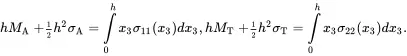
On using ( 2.235) and ( 2.236) it follows that
 (2.240)
 (2.241)
2.18.3 Some Special Cases
It is useful now to consider some important special cases that arise very often when considering the bending deformation of materials.
2.18.3.1 Four-point Bending Tests
The previous analysis can be used to determine the stress and strain state in beams subject to four-point bending. The analysis will apply near the mid-plane between the planes normal to the beam axis that contain the contact points of the inner rollers used in the experiments. For this case σA=σT=σt=MT=ΔT=0 and the relations ( 2.235), ( 2.236), ( 2.240) and ( 2.241) reduce to the form
 (2.242)
 (2.243)
 (2.244)
 (2.245)
It is clear from ( 2.242), ( 2.243) and ( 2.245) that
 (2.246)
From ( 2.215) 1, ( 2.244) and ( 2.246)
 (2.247)
 (2.248)
It is noted from ( 2.211) that the quantities ε¯A+12ε^Ah and ε¯T+12ε^Th appearing in ( 2.242), ( 2.243) and ( 2.246) are the in-plane strains on the mid-plane x3=12h (i.e. the neutral plane) which are zero for the loading case under consideration.
2.18.3.2 Plane Strain Bending
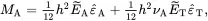
Plane strain bending conditions are characterised by a zero transverse strain everywhere in the beam so that ε¯T=ε^T=0. It is also assumed that σA=σt=ΔT=0. It then follows that the relations ( 2.235), ( 2.236), ( 2.240) and ( 2.241) reduce to
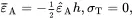 (2.249)
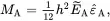 (2.250)
Интервал:
Закладка:
Похожие книги на «Properties for Design of Composite Structures»
Представляем Вашему вниманию похожие книги на «Properties for Design of Composite Structures» списком для выбора. Мы отобрали схожую по названию и смыслу литературу в надежде предоставить читателям больше вариантов отыскать новые, интересные, ещё непрочитанные произведения.


Обсуждение, отзывы о книге «Properties for Design of Composite Structures» и просто собственные мнения читателей. Оставьте ваши комментарии, напишите, что Вы думаете о произведении, его смысле или главных героях. Укажите что конкретно понравилось, а что нет, и почему Вы так считаете.