Neil McCartney - Properties for Design of Composite Structures
Здесь есть возможность читать онлайн «Neil McCartney - Properties for Design of Composite Structures» — ознакомительный отрывок электронной книги совершенно бесплатно, а после прочтения отрывка купить полную версию. В некоторых случаях можно слушать аудио, скачать через торрент в формате fb2 и присутствует краткое содержание. Жанр: unrecognised, на английском языке. Описание произведения, (предисловие) а так же отзывы посетителей доступны на портале библиотеки ЛибКат.
- Название:Properties for Design of Composite Structures
- Автор:
- Жанр:
- Год:неизвестен
- ISBN:нет данных
- Рейтинг книги:4 / 5. Голосов: 1
-
Избранное:Добавить в избранное
- Отзывы:
-
Ваша оценка:
Properties for Design of Composite Structures: краткое содержание, описание и аннотация
Предлагаем к чтению аннотацию, описание, краткое содержание или предисловие (зависит от того, что написал сам автор книги «Properties for Design of Composite Structures»). Если вы не нашли необходимую информацию о книге — напишите в комментариях, мы постараемся отыскать её.
A comprehensive guide to analytical methods and source code to predict the behavior of undamaged and damaged composite materials Properties for Design of Composite Structures: Theory and Implementation Using Software
Properties for Design of Composite Structures: Theory and Implementation Using Software
Properties for Design of Composite Structures — читать онлайн ознакомительный отрывок
Ниже представлен текст книги, разбитый по страницам. Система сохранения места последней прочитанной страницы, позволяет с удобством читать онлайн бесплатно книгу «Properties for Design of Composite Structures», без необходимости каждый раз заново искать на чём Вы остановились. Поставьте закладку, и сможете в любой момент перейти на страницу, на которой закончили чтение.
Интервал:
Закладка:
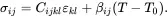 (2.153)
It should be noted that the stress components are zero everywhere when the strain is defined to be zero everywhere at the reference temperature T0.
The inverse form of the linear stress-strain relations ( 2.153) is written as
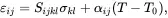 (2.154)
where the compliance tensor Sijkl is such that
 (2.155)
where use has been made of ( 2.15), and where
 (2.156)
are anisotropic thermal expansion coefficients.
2.14.1 Isotropic Materials
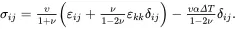
The situation simplifies when the material is linear thermoelastic and isotropic so that the stress-strain relations are
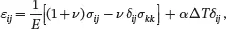 (2.157)
where E is Young’s modulus, ν is Poisson’s ratio, α is the thermal expansion coefficient and The inverse form is
 (2.158)
When the stress field is hydrostatic so that σij=−pδij, and because σkk≡σ11+σ22+σ33, it follows from (2.157) that
 (2.159)
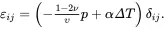
The inverse form ( 2.158) may be written as
 (2.160)
where λ and μ are Lamé’s constants, μ being the shear modulus, which can be calculated from Young’s modulus and Poisson’s ratio as follows:
 (2.161)
2.15 Introducing Contracted Notation
The general formulation for describing the elastic constants of anisotropic materials involves fourth-order tensors that are difficult to apply in many practical situations where analytical methods can be used. A simplified contracted notation is usually used for such analyses where the fourth-order tensors of elastic constants are replaced by a second-order matrix formulation that is now described. The matrix formulation makes use of the fact that the stress and strain tensors are symmetric. These symmetry properties enabled the derivation of the relationships ( 2.149)–( 2.151).
The components of the stress and strain components are now assembled in column vectors of length six so that
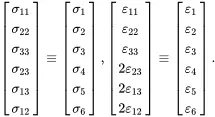 (2.162)
It should be noted that a factor of two has been applied only to the shear terms of the relation involving the strains so that the quantities 2εij for i≠j correspond to the widely used engineering shear strain values. General linear elastic stress-strain relations, including thermal expansion terms, have the contracted matrix form
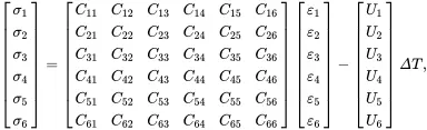 (2.163)
where CIJ are symmetric elastic constants, which are components of the second-order matrix C, and where UI are thermoelastic constants associated with the tensor βij, which are components of the vector U, the uppercase indices I and J ranging from 1 to 6. For orthotropic materials the stress-strain relations have the simpler matrix form
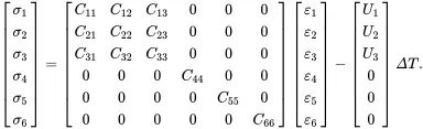 (2.164)
The stress-strain relations ( 2.163) may be written, using a repeated summation convention for uppercase indices over the range 1, 2, …, 6, as
 (2.165)
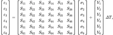
The inverse of the matrix CIJ is denoted by the symmetric matrix SIJ such that
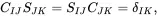 (2.166)
where δIK is the Kronecker delta symbol having the value 1 when I=J and the value 0 otherwise. On multiplying ( 2.165) on the left by SLI and on using ( 2.166), it can be shown that
 (2.167)
The quantities VI are the components of the vector Vwhich is associated with the thermal expansion tensor αij. The matrix form of ( 2.167) is given by
 (2.168)
and the corresponding orthotropic form is
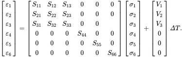 (2.169)
When expanded using the stress and strain tensor components and the symmetry of SIJ, the stress-strain relations may be written as
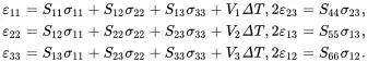 (2.170)
2.16 Tensor Transformations
When considering laminated composite materials, where each ply is reinforced with aligned straight fibres that are inclined at various angles to a global set of coordinates, there is a need to define a set of local coordinates aligned with the fibres in each ply. There is also a need to determine the properties of each ply referred to the global coordinates. For a right-handed set of global coordinates x 1, x 2and x 3, i 1, i 2and i 3are unit vectors for the directions of the x 1-, x 2- and x 3-axes, respectively. For laminate models, the fibres are usually assumed to be in the x 1-direction and coordinate transformations involve rotations about the x 3-axis. When modelling unidirectional plies as transverse isotropic materials the rotations would need to be taken about the x 1-axis if the fibres are in the x 1-direction. Coordinate transformations involving rotations about the x 3-axis are now considered.
Читать дальшеИнтервал:
Закладка:
Похожие книги на «Properties for Design of Composite Structures»
Представляем Вашему вниманию похожие книги на «Properties for Design of Composite Structures» списком для выбора. Мы отобрали схожую по названию и смыслу литературу в надежде предоставить читателям больше вариантов отыскать новые, интересные, ещё непрочитанные произведения.


Обсуждение, отзывы о книге «Properties for Design of Composite Structures» и просто собственные мнения читателей. Оставьте ваши комментарии, напишите, что Вы думаете о произведении, его смысле или главных героях. Укажите что конкретно понравилось, а что нет, и почему Вы так считаете.