Zhuming Bi - Computer Aided Design and Manufacturing
Здесь есть возможность читать онлайн «Zhuming Bi - Computer Aided Design and Manufacturing» — ознакомительный отрывок электронной книги совершенно бесплатно, а после прочтения отрывка купить полную версию. В некоторых случаях можно слушать аудио, скачать через торрент в формате fb2 и присутствует краткое содержание. Жанр: unrecognised, на английском языке. Описание произведения, (предисловие) а так же отзывы посетителей доступны на портале библиотеки ЛибКат.
- Название:Computer Aided Design and Manufacturing
- Автор:
- Жанр:
- Год:неизвестен
- ISBN:нет данных
- Рейтинг книги:3 / 5. Голосов: 1
-
Избранное:Добавить в избранное
- Отзывы:
-
Ваша оценка:
Computer Aided Design and Manufacturing: краткое содержание, описание и аннотация
Предлагаем к чтению аннотацию, описание, краткое содержание или предисловие (зависит от того, что написал сам автор книги «Computer Aided Design and Manufacturing»). Если вы не нашли необходимую информацию о книге — напишите в комментариях, мы постараемся отыскать её.
Computer Aided Design and Manufacturing being uniquely structured to classify and align engineering disciplines and computer aided technologies from the perspective of the design needs in whole product life cycles, utilizing a comprehensive Solidworks package (add-ins, toolbox, and library) to showcase the most critical functionalities of modern computer aided tools, and presenting real-world design projects and case studies so that readers can gain CAD and CAM problem-solving skills upon the CAD/CAM theory.
is an ideal textbook for undergraduate and graduate students in mechanical engineering, manufacturing engineering, and industrial engineering. It can also be used as a technical reference for researchers and engineers in mechanical and manufacturing engineering or computer-aided technologies.
Computer Aided Design and Manufacturing — читать онлайн ознакомительный отрывок
Ниже представлен текст книги, разбитый по страницам. Система сохранения места последней прочитанной страницы, позволяет с удобством читать онлайн бесплатно книгу «Computer Aided Design and Manufacturing», без необходимости каждый раз заново искать на чём Вы остановились. Поставьте закладку, и сможете в любой момент перейти на страницу, на которой закончили чтение.
Интервал:
Закладка:
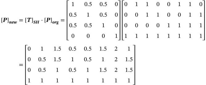
The coordinate transformation matrix for an object with a shearing transformation is represented as (TutorialsPoint 2018)
(2.8) 
where [ T] SHis the shearing transformation matrix, d , g , i , b , c , f are the shearing factors of yalong x, zalong x, zalong y, xalong y, xalong z, and yalong z, respectively. A shearing is a relative angle deformation between two axes. Therefore, [ T] SHhas to be symmetric, i.e. b = d , g = c , and i = f . In other words, [ T] SHonly has three independent variables.
For a point Pin its homogeneous coordinate ( x , y , z , 1), Eq. (2.8) is applied to define its new position P′ ( x′ , y′ , z′ , 1) as
(2.9) 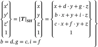
Example 2.3
Given a cube with the size of 1 × 1 × 1 at its origin in Figure 2.13, assume that node 1 is fixed and node 5 is sheared from (1, 1, 1) to (2, 2, 2), and determine the matrix for 3D shearing and the new positions of all vertices after shearing.
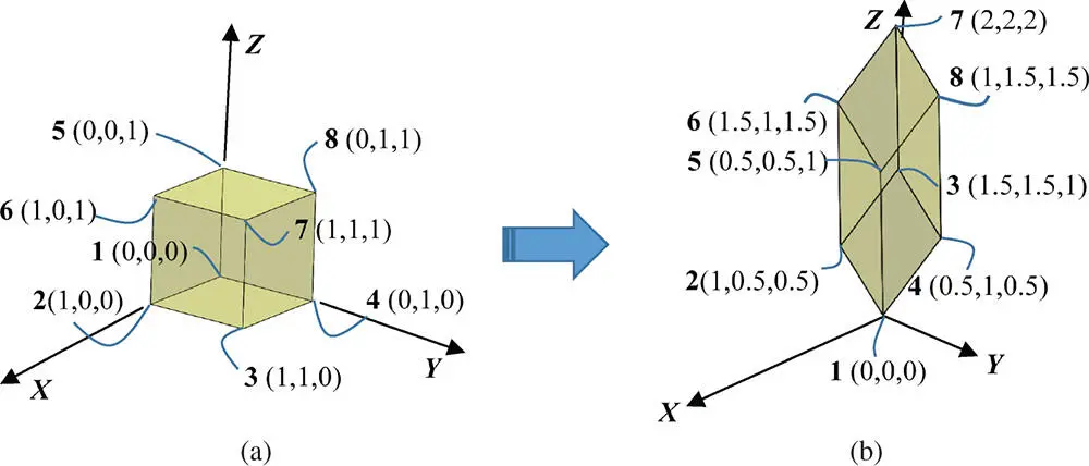
Figure 2.13Example of the 3D shearing transformation of an object. (a) Before transformation. (b) After transformation.
Solution
To determine the shearing matrix, six independent variables must be determined in Eq. (2.9). Since the positions of nodes 1 and 5 are known before and after shearing, Eq. (2.9) is applied to determine the conditions that these variables must satisfy:
(2.10) 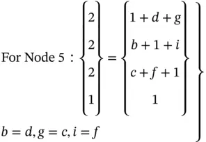
Solving Eq. (2.10) gives b = d = c = g = f = i = 0.5.
Figure 2.13b shows the sheared object whose vertices after shearing are determined as
The elements a to j in the reflection transformation matrix of Eq. (2.7) can also be determined for a rotation transformation matrix along an axis in a 3D space. The corresponding matrix can be derived from the rotational matrices for the points in Table 2.1. Figure 2.14shows the rotational transformation matrices when x, y, and zare chosen as a rotational axis for a rotational angle of θ x, θ y, and θ z, respectively.
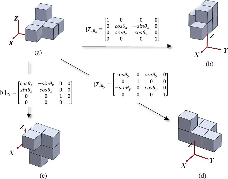
Figure 2.14Rational coordinate transformation of an object. (a) Object in the original position. (b) The x ‐axis rotation ( θ x). (c) The z ‐axis rotation ( θ z). (d) The y ‐axis rotation ( θ y).
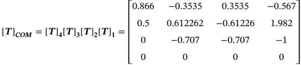
A series of the coordinate transformations, such as translation, scaling, shearing, rotation, and reflection, can be combined as a comprehensive transformation of a point or object. In such a case, the combined transformation matrix can be determined as
(2.11) 
where [ T] COMis the combined transformation matrix, i = 1, 2, …, N is the order of N transformation operations, and [ T ] iis the transformation matrix for the i th operation.
Note that the order of the multiplications of the matrices is reversed with that of the operations.
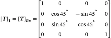
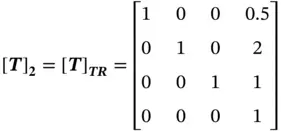
Example 2.4
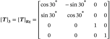
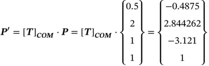
Given a point P (1, 3, 2) in a reference coordinate system ( O‐XYZ), determine its new position P′ after the following operations: (i) rotate 45° with respect to the Xaxis, (ii) translate it with a vector of (0.5, 2, 1), (iii) rotate −30° with respect to the Zaxis, and (iv) mirror the position about the XYplane.
Solution
Using the coordinate transformations in Table 2.1, the corresponding transformation matrix of each operation is determined as follows:
 |
 |
|
 |
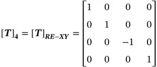 |
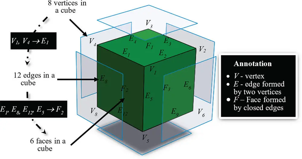
Figure 2.15Vertices, edges, and faces of a solid.
Therefore, using Eq. (2.11),
2.3 Representation of Shapes
A solid object has a geometric shape. A solid model is a digital representation of the geometry of an existing or envisioned physical object. A solid can be modelled in two basic methods: (i) designers may specify points, curves, and surfaces to define the mathematical representation of boundary surfaces and knit them together as a finite volume of the object; (ii) designers may select the models of simple shapes, such as blocks or cylinders, with specified dimensions, positions, and orientations, and combine them using logic operations such as union, intersection, and difference. The resulting representation is an unambiguous, complete, and detailed digital approximation of the object geometry or an assembly of objects (such as a car engine or an entire aeroplane).
Figure 2.15shows that a solid object must be a watertight fine volume ( B ), which is defined by a number of boundary faces ( F ). In turn, a face F consists of a number of edges ( E ) and an edge E consists of a number of vertices ( V ). The information about vertices, edges, faces, and volumes is at different levels. In order to work with the solid models in the computer systems, they should be stored in the computer memory, which allows processing, converting, and ultimately displaying them. Different data structures can be used to represent solids.
Читать дальшеИнтервал:
Закладка:
Похожие книги на «Computer Aided Design and Manufacturing»
Представляем Вашему вниманию похожие книги на «Computer Aided Design and Manufacturing» списком для выбора. Мы отобрали схожую по названию и смыслу литературу в надежде предоставить читателям больше вариантов отыскать новые, интересные, ещё непрочитанные произведения.


Обсуждение, отзывы о книге «Computer Aided Design and Manufacturing» и просто собственные мнения читателей. Оставьте ваши комментарии, напишите, что Вы думаете о произведении, его смысле или главных героях. Укажите что конкретно понравилось, а что нет, и почему Вы так считаете.