Zhuming Bi - Computer Aided Design and Manufacturing
Здесь есть возможность читать онлайн «Zhuming Bi - Computer Aided Design and Manufacturing» — ознакомительный отрывок электронной книги совершенно бесплатно, а после прочтения отрывка купить полную версию. В некоторых случаях можно слушать аудио, скачать через торрент в формате fb2 и присутствует краткое содержание. Жанр: unrecognised, на английском языке. Описание произведения, (предисловие) а так же отзывы посетителей доступны на портале библиотеки ЛибКат.
- Название:Computer Aided Design and Manufacturing
- Автор:
- Жанр:
- Год:неизвестен
- ISBN:нет данных
- Рейтинг книги:3 / 5. Голосов: 1
-
Избранное:Добавить в избранное
- Отзывы:
-
Ваша оценка:
Computer Aided Design and Manufacturing: краткое содержание, описание и аннотация
Предлагаем к чтению аннотацию, описание, краткое содержание или предисловие (зависит от того, что написал сам автор книги «Computer Aided Design and Manufacturing»). Если вы не нашли необходимую информацию о книге — напишите в комментариях, мы постараемся отыскать её.
Computer Aided Design and Manufacturing being uniquely structured to classify and align engineering disciplines and computer aided technologies from the perspective of the design needs in whole product life cycles, utilizing a comprehensive Solidworks package (add-ins, toolbox, and library) to showcase the most critical functionalities of modern computer aided tools, and presenting real-world design projects and case studies so that readers can gain CAD and CAM problem-solving skills upon the CAD/CAM theory.
is an ideal textbook for undergraduate and graduate students in mechanical engineering, manufacturing engineering, and industrial engineering. It can also be used as a technical reference for researchers and engineers in mechanical and manufacturing engineering or computer-aided technologies.
Computer Aided Design and Manufacturing — читать онлайн ознакомительный отрывок
Ниже представлен текст книги, разбитый по страницам. Система сохранения места последней прочитанной страницы, позволяет с удобством читать онлайн бесплатно книгу «Computer Aided Design and Manufacturing», без необходимости каждый раз заново искать на чём Вы остановились. Поставьте закладку, и сможете в любой момент перейти на страницу, на которой закончили чтение.
Интервал:
Закладка:
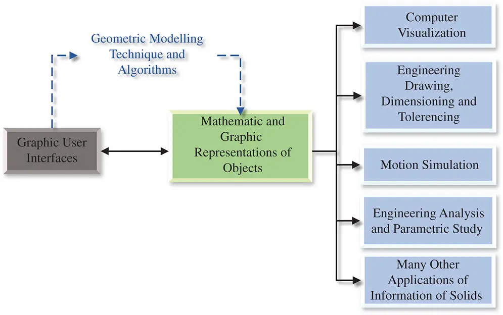
Figure 2.1Role of geometric modelling in computer aided systems (CAD).
2.2 Basic Elements in Geometry
Geometry relates to the properties and relations of basic geometric elements such as points , lines , surfaces , solids , and higher dimensional analogues.
Figure 2.2shows an example of basic geometric elements of an object. An object is represented by its geometric elements such as points , edges , surfaces , and solids . In addition, basic geometric elements are at different levels of the topological tree of an object. As shown in Figure 2.2, points and nodes are at the lowest level, edges formed by points or nodes are at the second level, surfaces formed by the boundary edges are at the third level, and solids with a given volume formed by a set of watertight boundary surfaces are at the upper level.
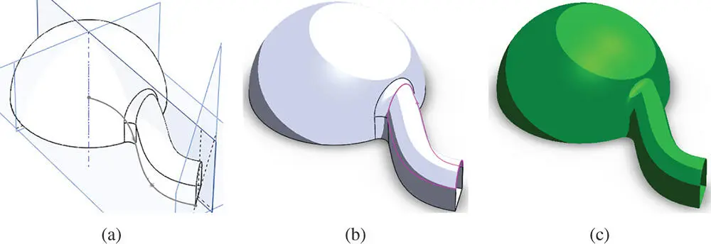
Figure 2.2Example of basic geometric elements. (a) Points, nodes, lines, edges, axes, and planes. (b) Patches, surfaces, and operations. (c) Volumes, features, solids, and operations.
Geometry includes the relations of these geometric elements. These relations can be spatial or topological . To represent spatial relations of geometric elements, some references have to be established, and common references can be points , axes , planes , and coordinate systems . To represent topological relations, one has to be familiar with some common logical operations such as union , subtraction , and intersection .
2.2.1 Coordinate Systems
Any geometric element in a three‐dimensional space has six degrees of freedom (DOF). To describe the spatial relation between two geometric elements in solids, a reference coordinate system must be established. Figure 2.3shows three most commonly used coordinate systems (CSs), i.e. a Cartesian coordinate system , cylindrical coordinate system , and spherical coordinate system .
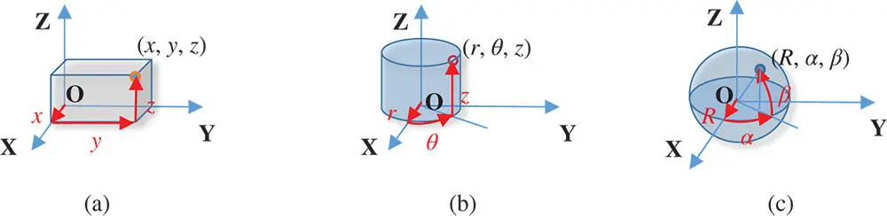
Figure 2.3Three commonly used coordinate systems. (a) Cartesian coordinate system. (b) Cylindrical coordinate system. (c) Spherical coordinate system.
A Cartesian CS consists of three axes that are mutually perpendicular to each other. A position in the Cartesian CS is defined by its distances to the origin ( x , y , z ) projected on three axes ( X , Y , Z ). A cylindrical CS consists of two linear axes ( X and Z ) and one rotational axis. Correspondingly, a position in the cylindrical CS is defined by two scalar variables and one angular variable, i.e. ( r , θ , z ). A spherical CS consists of two rotational axes and one translational axis. The position of a point in the spherical CS is specified by three variables: the radial distance ( R ) of that point from a fixed origin, its polar angle ( α ) measured from a fixed zenith direction, and the azimuth angle ( β ) of its orthogonal projection on a reference plane that passes through the origin and is orthogonal to the zenith, measured from a fixed reference direction on that plane, ( R , α, β ).
A user of a CAD system should always be aware that a reference CS is essential for geometric modelling of objects in computers. As shown in Figure 2.4, any commercial CAD software comes with a default coordinate system in modelling templates. The default coordinate system is usually a Cartesian CS. In Figure 2.4, the default Cartesian CS is O – XYZand the planes of O – XY, O – XZ, O – YZ are defined as a default front plane , top plane , and right plane , respectively.
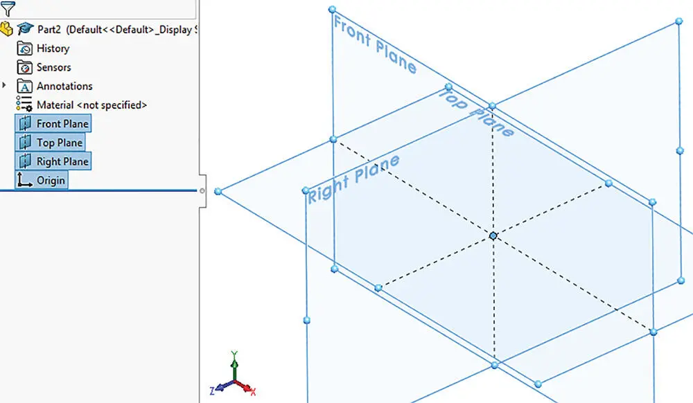
Figure 2.4Default Cartesian CS in a CAD system.
2.2.2 Reference Points, Lines, and Planes
Other than the references of coordinate systems, other elements such as points, lines, and planes can also be used as the references in geometric modelling. Moreover, geometric elements at a high level can be represented by a number of points at the lowest level. Figure 2.5shows a point in the reference CS that is completely defined by giving its three coordinate values ( x , y , z ) along x‐ , y‐ , and z ‐axes. For a given geometric element, the same amount of information can be defined in many different ways. For example, a point P is relevant to the high‐level elements such as lines or surfaces in the sense that a point can be an end‐point of these elements. Therefore, a reference point can be defined directly based on its relations to existing geometric elements.
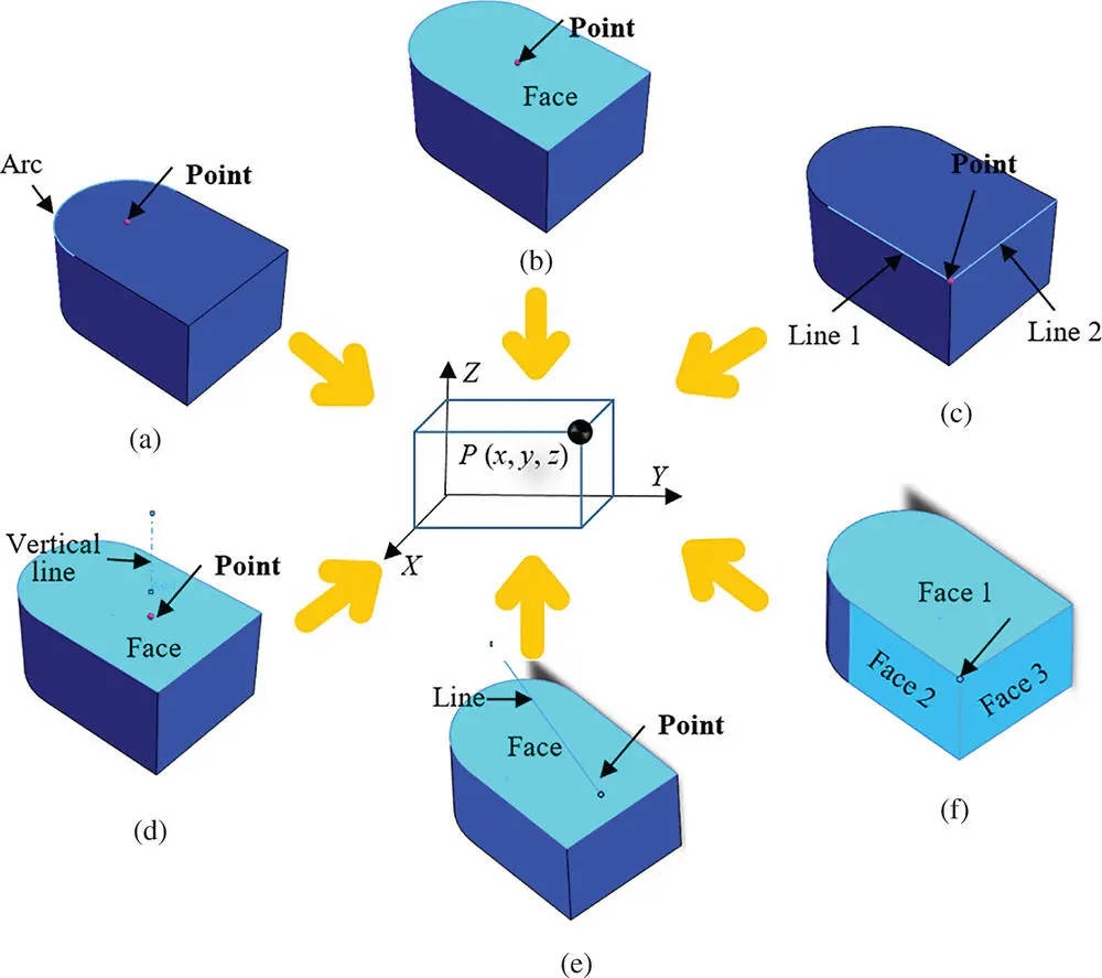
Figure 2.5The definition of a point from existing reference geometries. (a) Arc centre. (b) Centre of face. (c) Intersection of two lines. (d) Projection of a vertical line on a plane. (e) Interaction of a line and plane. (f) Interaction of three planes.
Figure 2.5shows that a point can be defined in many different ways: Figure 2.5a to f shows that the point is defined as the centre of an arc, the centre of a face, the interaction of two lines that interact, the projected points of a vertical line on a plane, the intersection of a line and a plane, and the intersection of three planes, respectively.
Mathematically, a point Pin the Cartesian coordinate system can be represented as
(2.1) 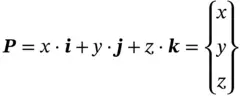
where x , y , and z are the coordinates and i, j, and kare the unit vectors along the axes of X, Y, and Z, respectively.
As shown in Figure 2.6b, a line Lin the Cartesian coordinate system can be represented as the line segment connected by two points P 1( x 1, y 1, z 1) and P 2( x 2, y 2, z 2) as
(2.2) 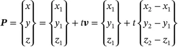
where vis the vector along the line determined by P 1and P 2, t is an independent variable, and P( x , y , z ) is an arbitrary point on the line.
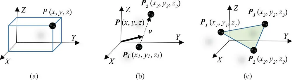
Figure 2.6Using points to represent lines and planes. (a) Point. (b) Line. (c). Plane.
Читать дальшеИнтервал:
Закладка:
Похожие книги на «Computer Aided Design and Manufacturing»
Представляем Вашему вниманию похожие книги на «Computer Aided Design and Manufacturing» списком для выбора. Мы отобрали схожую по названию и смыслу литературу в надежде предоставить читателям больше вариантов отыскать новые, интересные, ещё непрочитанные произведения.


Обсуждение, отзывы о книге «Computer Aided Design and Manufacturing» и просто собственные мнения читателей. Оставьте ваши комментарии, напишите, что Вы думаете о произведении, его смысле или главных героях. Укажите что конкретно понравилось, а что нет, и почему Вы так считаете.