Donald W. McRobbie - Essentials of MRI Safety
Здесь есть возможность читать онлайн «Donald W. McRobbie - Essentials of MRI Safety» — ознакомительный отрывок электронной книги совершенно бесплатно, а после прочтения отрывка купить полную версию. В некоторых случаях можно слушать аудио, скачать через торрент в формате fb2 и присутствует краткое содержание. Жанр: unrecognised, на английском языке. Описание произведения, (предисловие) а так же отзывы посетителей доступны на портале библиотеки ЛибКат.
- Название:Essentials of MRI Safety
- Автор:
- Жанр:
- Год:неизвестен
- ISBN:нет данных
- Рейтинг книги:4 / 5. Голосов: 1
-
Избранное:Добавить в избранное
- Отзывы:
-
Ваша оценка:
Essentials of MRI Safety: краткое содержание, описание и аннотация
Предлагаем к чтению аннотацию, описание, краткое содержание или предисловие (зависит от того, что написал сам автор книги «Essentials of MRI Safety»). Если вы не нашли необходимую информацию о книге — напишите в комментариях, мы постараемся отыскать её.
Reflects the most current research, guidelines, and MRI safety information Explains procedures for scanning pregnant women, managing MRI noise exposure, and handling emergency situations Prepares candidates for the American Board of MR Safety exam and other professional certifications Aligns with MRI safety roles such as MR Medical Director (MRMD), MR Safety Officer (MRSO) and MR Safety Expert (MRSE) Contains numerous illustrations, figures, self-assessment tests, key references, and extensive appendices
is an indispensable text for all radiographers and radiologists, as well as physicists, engineers, and researchers with an interest in MRI.
Essentials of MRI Safety — читать онлайн ознакомительный отрывок
Ниже представлен текст книги, разбитый по страницам. Система сохранения места последней прочитанной страницы, позволяет с удобством читать онлайн бесплатно книгу «Essentials of MRI Safety», без необходимости каждый раз заново искать на чём Вы остановились. Поставьте закладку, и сможете в любой момент перейти на страницу, на которой закончили чтение.
Интервал:
Закладка:
(2.27) 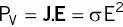
Specific absorption rate (SAR) is defined as the power deposited in tissue per unit mass given by
(2.28) 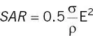
ρ is tissue density. In the simplest case of a uniform sphere, the maximum SAR from a rectangular constant amplitude B 1pulse repeated N times is [5]
(2.29) 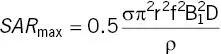
The duty cycle D is the fraction of time for which the B 1pulse (duration t p) is active within the MRI sequence TR period:
(2.30) 
The average SAR is
(2.31) 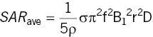
For a sphere, the average SAR is 0.4 of the peak SAR. In terms of flip angle α, for a rectangular B 1pulse
(2.32) 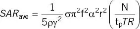
This illustrates the well‐known result that SAR is proportional to the square of the flip angle (for a given pulse shape), increases linearly with the number of RF pulses and is inversely proportional to the pulse duration and sequence repetition time TR.
In general, calculating SAR for arbitrary geometries requires the use of numerical methods [6]. An additional issue arises as a consequence of Ampere’s law (Maxwell’s fourth equation) for frequencies above 10 MHz, in that the induced E, itself, induces an RF magnetic field opposed to B 1resulting in an overestimation of SAR. Additionally, differing tissue properties, anatomical geometry, and the presence of metallic implants will alter the RF deposition pattern, often resulting in SAR hotspots. The relationship between SAR and heating is non‐linear and heterogeneous and is heavily influenced by the thermal properties of tissue and cooling from perfusion and conduction. These will be considered in Chapter 5.
Wave‐like behavior of B 1
Figure 1.26showed the uniformity of the B 1‐field in air produced by a typical birdcage transmit coil. However, the presence of the patient’s tissues affects the nature and amplitude of the field ( Figure 2.28). In a dielectric medium the EM wavelength λ has a different value than in air or vacuum and the familiar equation for wavelength (λ = c/f) becomes
(2.33) 
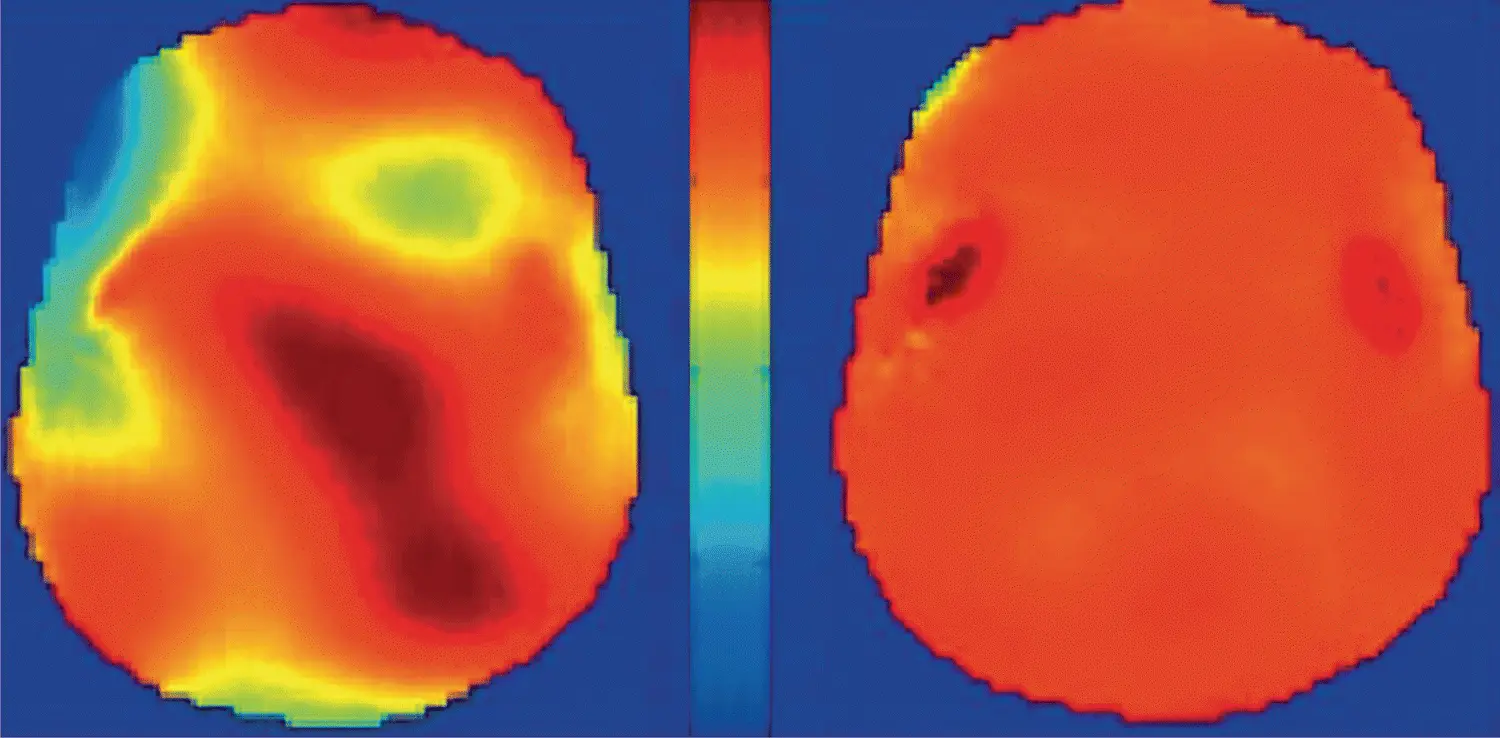
Figure 2.28 B 1uniformity map for a head phantom at 7 T showing the effect of (left) non‐optimized and (right) optimized parallel transmission. Figure courtesy of Kawin Setsompop, Massachusetts General Hospital, A.A. Martinos Center for Biomedical Imaging.
where c is the speed of light (3×10 8ms −1).
The “wavelength” in air is around 4.7 m at 64 MHz (1.5 T) and 2.3 m at 128 MHz (3 T) and B 1in air is a magnetic field in the near field region with minimal E‐field components, except close to the coil windings and tuning capacitors. However, the dielectric constant, ε rof tissues changes the wavelength within the patient. Often the relative permittivity ε rof water, with a value stated to be around 80, is used to estimate wavelength in tissue. This reduces the wavelength at 64 and 128 MHz to 0.51 m and 0.26 m. These dimensions are comparable to the patient’s dimensions and also to the body transmit coil dimensions.
Near and far field
In order to better understand the RF interactions, we can consider radio antenna theory. In radio transmission for broadcasting and telecommunications, the RF field is commonly divided into different regions illustrated in Figure 2.29. Closest to the transmitter is the reactive or inductive near field . This is the mode of operation of the MR transmit coil, producing primarily a magnetic B 1‐field. This region is said to extend to λ/2π or 0.159×λ. In a 1.5 T scanner this would extend in air to 0.75 m from the iso‐centre and half that distance for a 3 T scanner, encompassing the entire coil volume.
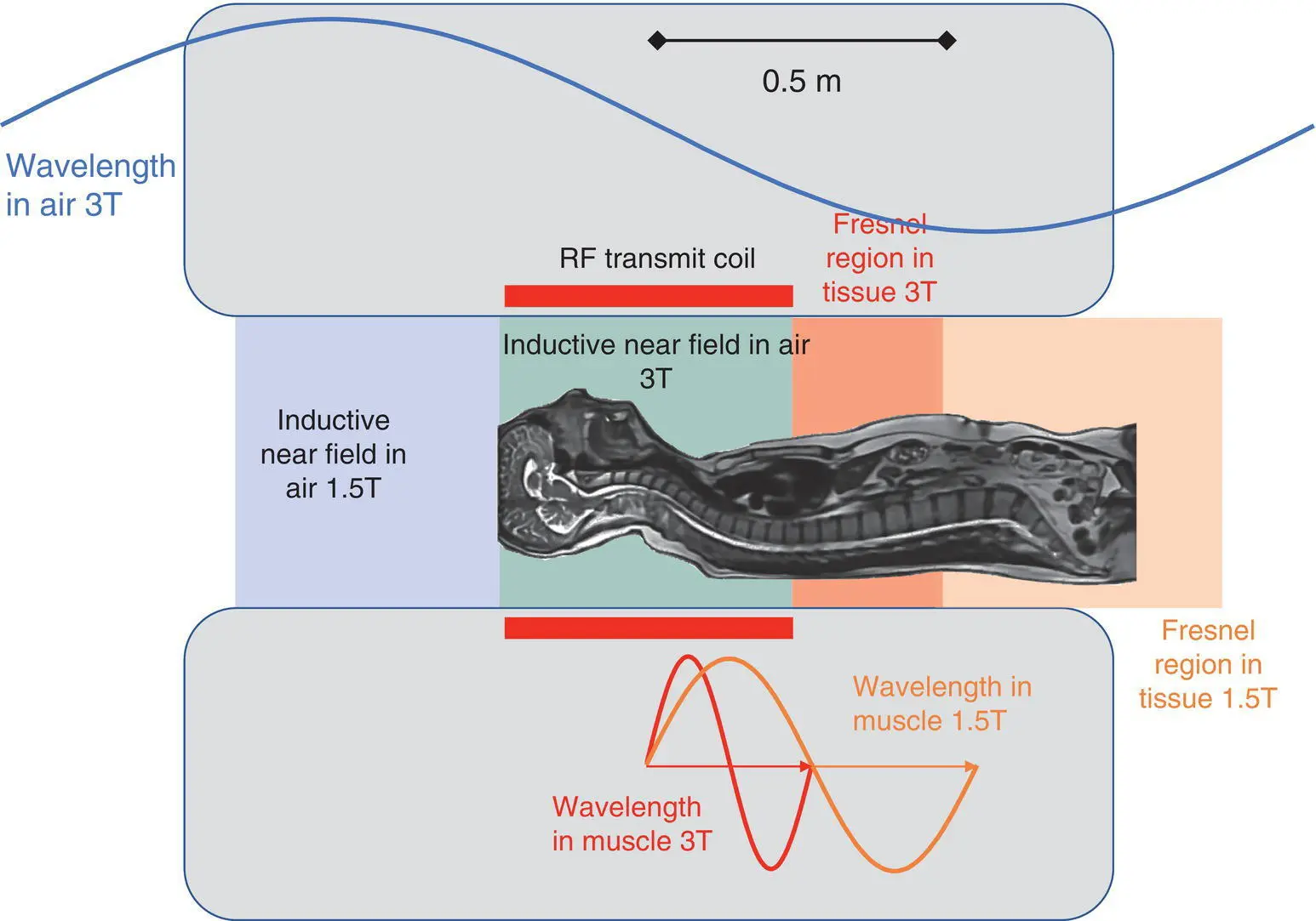
Figure 2.29 Field regions in air and within the patient’s tissues. In the inductive near field zone the B 1magnetic field dominates. In the radiative near field B 1and E 1are highly non‐uniform. For comparison the wavelengths in air and muscle are shown. Top view of the scanner bore.
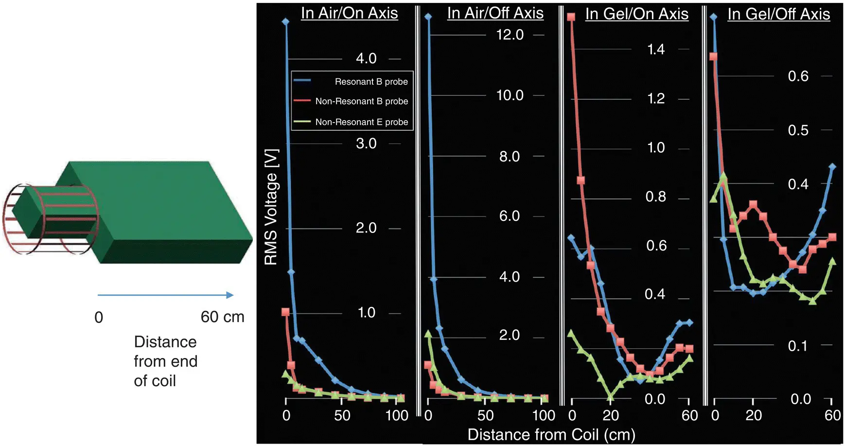
Figure 2.30Measurements of B 1and E 1in a gel phantom on axis and off‐axis up to 60 cm from the end of a transmit head coil in tissue equivalent material.
Source [8]. Licenced under CC BY 4.0. Licensee Frontiers.
The radiative near field or Fresnel region extends between one and two wavelengths. At 3 T with a patient in situ , this region will extend from 0.25 to 0.5 m and double those distances in a 1.5 T scanner. In the Fresnel zone the field behavior can become very complex with local maxima and minima. This results in the B and E fields extending well beyond the end of the coil within tissue. Figure 2.23shows measurements of B and E in a phantom where significant amounts of both fields exist up to 60 cm beyond the end of a head only transmit coil , i.e. well beyond where we might otherwise consider the RF field to end [7] . This behavior has implications for patients with implants.
MYTHBUSTER:
With a patient lying in the bore, the RF field extends significantly beyond the confines of the transmit coil. This is consequence of Maxwell’s Equations.
λ/2 resonant length
A better‐known effect of the wavelength change in tissue is the creation of standing waves or resonances when a conductor length is close to one half wavelength λ/2. This has particular importance for the avoidance of heating in active implants with lead lengths equal to or close to λ/2. Often the resonant lengths 13 cm and 26 cm are cited, but different tissues have a range of values:
muscle λ/2 = 14.7 cm at 128 MHz
fat λ/2 = 33.3 cm at 128 MHz
cancellous bone λ/2 = 22.9 cm at 128 MHz
cortical bone λ/2 = 30.6 cm at 128 MHz.
MYTHBUSTER:
The resonant length differs from 13 or 26 cm for most tissues at 1.5 and 3 T, and much broader resonant behavior is likely.
The final zone, is the far field or Fraunhofer region which occurs at distances much greater than a wavelength. In this region, we have fully formed electromagnetic plane waves whose intensity decreases with the inverse square law. Their intensity is measured as power density (in W m −2), but in MRI is very low – only relevant in terms of EM interference on other equipment.
Читать дальшеИнтервал:
Закладка:
Похожие книги на «Essentials of MRI Safety»
Представляем Вашему вниманию похожие книги на «Essentials of MRI Safety» списком для выбора. Мы отобрали схожую по названию и смыслу литературу в надежде предоставить читателям больше вариантов отыскать новые, интересные, ещё непрочитанные произведения.


Обсуждение, отзывы о книге «Essentials of MRI Safety» и просто собственные мнения читателей. Оставьте ваши комментарии, напишите, что Вы думаете о произведении, его смысле или главных героях. Укажите что конкретно понравилось, а что нет, и почему Вы так считаете.