Donald W. McRobbie - Essentials of MRI Safety
Здесь есть возможность читать онлайн «Donald W. McRobbie - Essentials of MRI Safety» — ознакомительный отрывок электронной книги совершенно бесплатно, а после прочтения отрывка купить полную версию. В некоторых случаях можно слушать аудио, скачать через торрент в формате fb2 и присутствует краткое содержание. Жанр: unrecognised, на английском языке. Описание произведения, (предисловие) а так же отзывы посетителей доступны на портале библиотеки ЛибКат.
- Название:Essentials of MRI Safety
- Автор:
- Жанр:
- Год:неизвестен
- ISBN:нет данных
- Рейтинг книги:4 / 5. Голосов: 1
-
Избранное:Добавить в избранное
- Отзывы:
-
Ваша оценка:
Essentials of MRI Safety: краткое содержание, описание и аннотация
Предлагаем к чтению аннотацию, описание, краткое содержание или предисловие (зависит от того, что написал сам автор книги «Essentials of MRI Safety»). Если вы не нашли необходимую информацию о книге — напишите в комментариях, мы постараемся отыскать её.
Reflects the most current research, guidelines, and MRI safety information Explains procedures for scanning pregnant women, managing MRI noise exposure, and handling emergency situations Prepares candidates for the American Board of MR Safety exam and other professional certifications Aligns with MRI safety roles such as MR Medical Director (MRMD), MR Safety Officer (MRSO) and MR Safety Expert (MRSE) Contains numerous illustrations, figures, self-assessment tests, key references, and extensive appendices
is an indispensable text for all radiographers and radiologists, as well as physicists, engineers, and researchers with an interest in MRI.
Essentials of MRI Safety — читать онлайн ознакомительный отрывок
Ниже представлен текст книги, разбитый по страницам. Система сохранения места последней прочитанной страницы, позволяет с удобством читать онлайн бесплатно книгу «Essentials of MRI Safety», без необходимости каждый раз заново искать на чём Вы остановились. Поставьте закладку, и сможете в любой момент перейти на страницу, на которой закончили чтение.
Интервал:
Закладка:
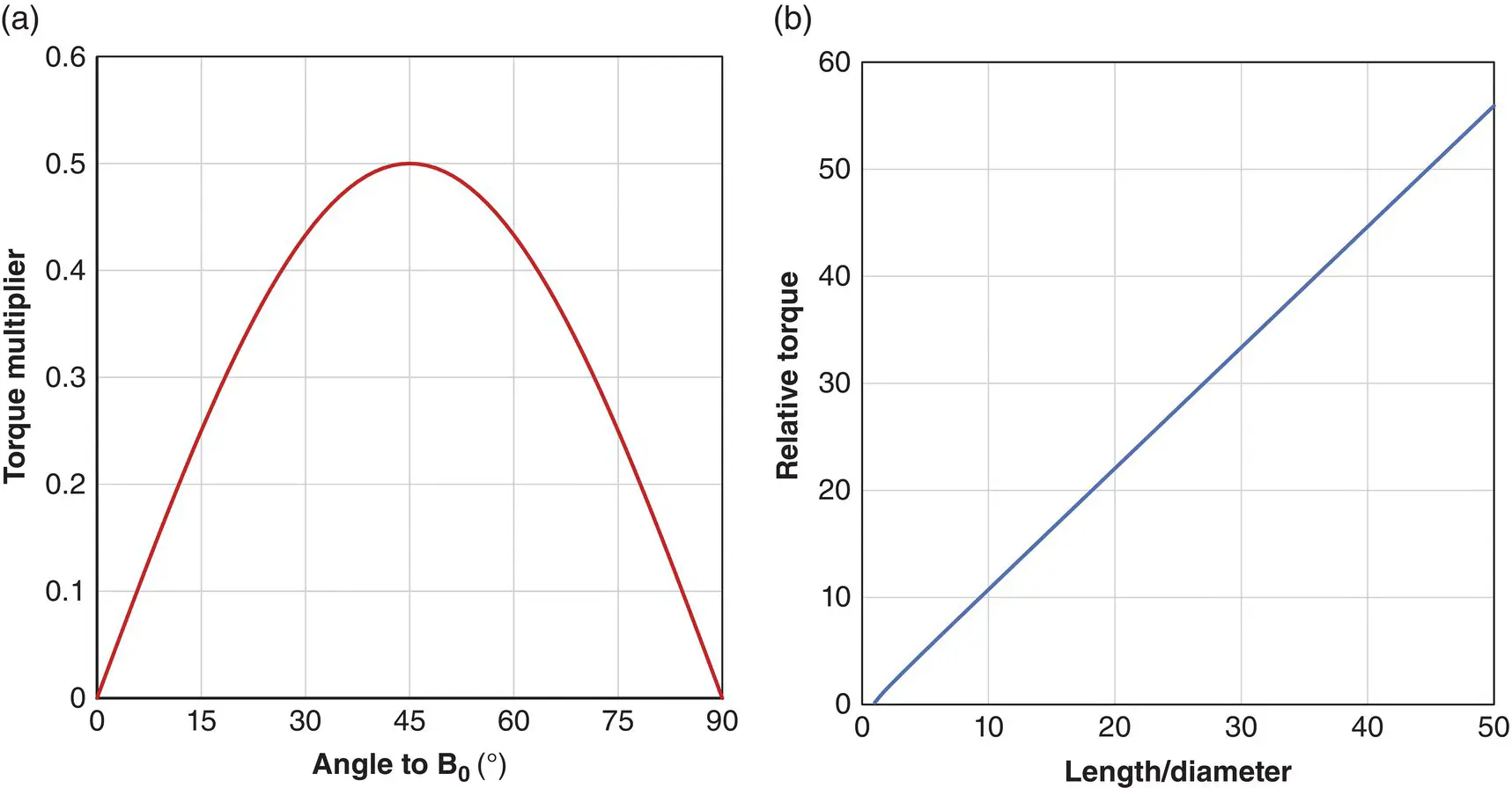
Figure 2.22 Relative torque as a function of: (a) angle; (b) ratio of length‐diameter for a cylinder for unsaturated ferromagnetic objects.
As χ << 1, the torque on non‐ferromagnetic objects is very small.
Example 2.7 Torque on a weakly ferromagnetic magnetic implant
Suppose an implant of length 1 cm, diameter 0.2 cm is introduced into a 3 T scanner at 45° to the z‐axis, what is the torque and twisting force if the implant has χ = 0.01?
As χ is small, treat the implant as paramagnetic. Calculate the volume and use Equation 2.15

The torque is then

and the rotational force is
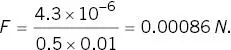
This is around one third of the force due to gravity .
MYTHBUSTER:
The maximum torque does not occur when an object is at a right angle to B 0, but at 45°.
Torque on soft ferromagnetic objects
Of more significance is the torque on a soft ferromagnetic object. The torque on an unsaturated object is
(2.17) 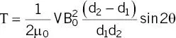
Remarkably this is also independent of susceptibility, depending upon the square of B 0(so four times greater at 3 T compared with 1.5 T), with a maximum value within the magnet bore. Torque becomes larger for long needle‐like objects ( Figure 2.22b). For a saturated object the torque becomes proportional to B sat 2and has a maximum value ( Figure 2.23)
(2.18) 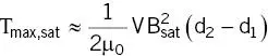
Figure 2.23 Predicted torque for ferromagnetic 0.1 kg objects of varying l/d ratios, with density 8000 kg m −3, susceptibility of 1000 and B sat= 2 T on the axis of a 1.5 T shielded magnet. The bore entrance is at 0.8 m.
Usually an object will twist long before it reaches the bore, and hence the torque rapidly disappears, aligning the object for maximum projectile velocity. There is the possibility of serious injury if an implant is ferromagnetic.
MYTHBUSTER:
Torque on strongly ferromagnetic objects is independent of their magnetic susceptibility.
Example 2.8 Torque on a ferromagnetic cylinder
You can use Figure 2.22and Equation 2.18to calculate the torque on a ferromagnetic object which saturates at 1 T. Suppose a cylinder is at 30° to B 0, and is 50 cm long, 10 cm diameter.
From the figure the multiplier for the angle is 0.43 and for the l/d ratio is 5. The volume is

The torque is then
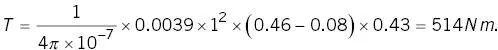
The force exerted on the ends of the object is given by the torque divided by half the length = 2057 N .
Torque v translational force
A question of some significance, especially for implants, is which is stronger, the translational or the twisting force? Figure 2.24shows the attractive and twisting force (from the torque) for ferromagnetic objects (mass 0.1 kg, density of 8000 kg m −3, χ = 1000) approaching a 3 T scanner. We assume that the orientation is such to produce either the maximum torque or translation (note: that these conditions are inconsistent with each other). What is quite surprising is that, in this simulation, the force exerted from twisting is greater than that from translation at most locations. This is bad news for MR safety as the first thing to occur will be the twisting to align with the field direction which is then the optimum orientation for projectiles. Also, for ferromagnetic implants, unless they are perfectly spherical (in which case the torque will be zero) or perfectly aligned with B 0, the twisting forces will persist for the whole time spent in the bore of the magnet. In the figure the forces on a 5 cm long needle (l/d = 50) are shown, where the twisting can greatly exceed the projectile force. Although the attractive force on the needle appears low, remember that items tend to accelerate into the scanner with high velocities, so this situation is very dangerous.
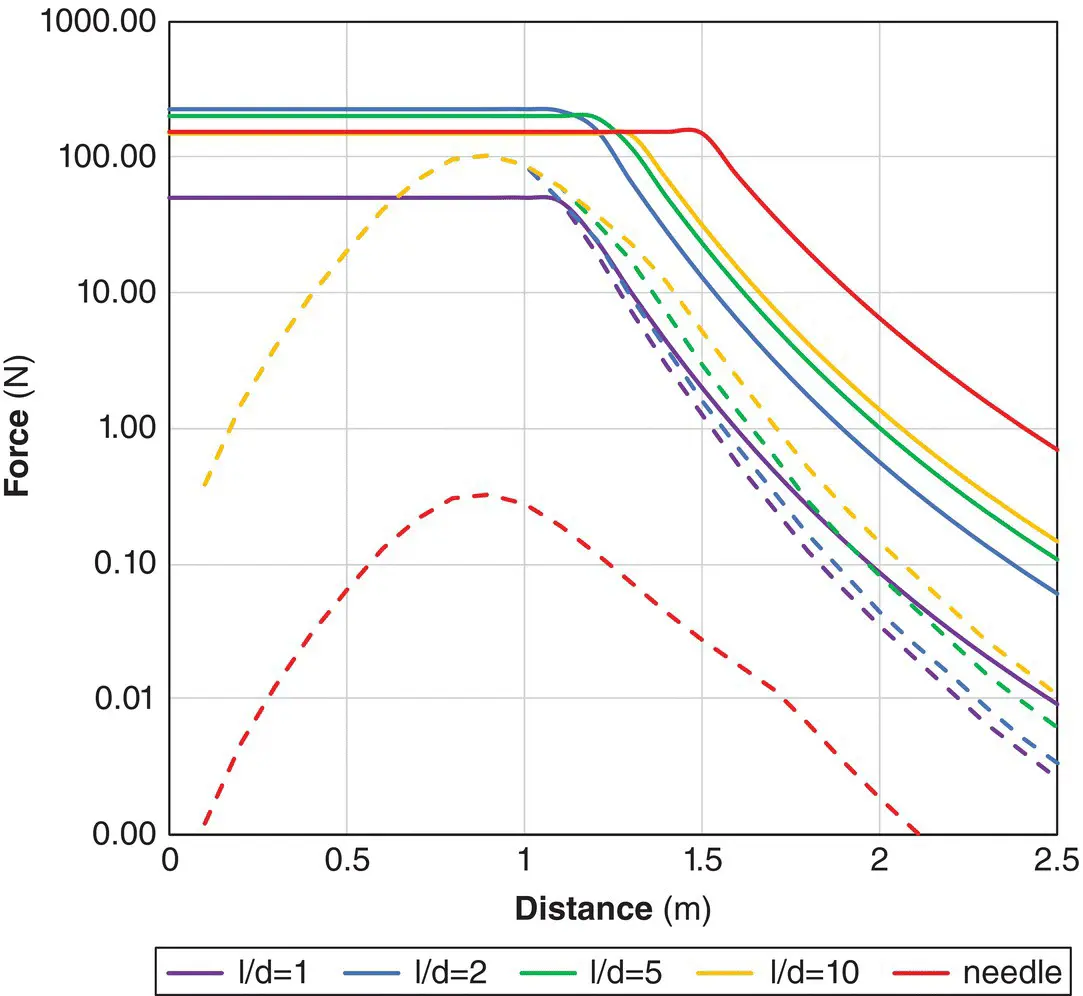
Figure 2.24 Predicted maximum twisting force (solid lines) and translational (dashed lines) from ferromagnetic 0.1 kg cylinders of varying l/d ratios and a 5 cm needle with l/d = 50, with densities 8000 kg m −3, χ = 1000 and B sat= 2 T on the axis of a 1.5 T shielded magnet. The lengths of the cylinders are 11.6, 7.5, 5, and 2.5 cm.
Forces on circuits
We saw in Chapter 1that the tesla was defined in terms of a force upon a moving charge. A moving charge is an electrical current, so it is no surprise that magnetic fields exert a force on a current‐carrying conductor.
Force on a straight conductor
The force on a current‐carrying conductor at an angle θ to B 0is ( Figure 2.25a):
(2.19) 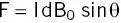
Figure 2.25 The Lorentz force on a straight conductor with (a) B into the page; (b) Fleming’s left‐hand rule scheme to deduce the direction of the force.
This follows Fleming’s left‐hand rule : if your forefinger points along B 0, your other fingers show the direction of current flow, then your thumb indicates the direction of the force ( Figure 2.25b).
Example 2.9 Force on an electrical wire
What is the force on a 10 cm length of wire at an angle 45° to a B 0of 1.5 T and carrying 10 A?

If the wire weighs 10 g, then this force is ten times the gravitational force on the wire .
Читать дальшеИнтервал:
Закладка:
Похожие книги на «Essentials of MRI Safety»
Представляем Вашему вниманию похожие книги на «Essentials of MRI Safety» списком для выбора. Мы отобрали схожую по названию и смыслу литературу в надежде предоставить читателям больше вариантов отыскать новые, интересные, ещё непрочитанные произведения.


Обсуждение, отзывы о книге «Essentials of MRI Safety» и просто собственные мнения читателей. Оставьте ваши комментарии, напишите, что Вы думаете о произведении, его смысле или главных героях. Укажите что конкретно понравилось, а что нет, и почему Вы так считаете.